


Chapter 2
2-17
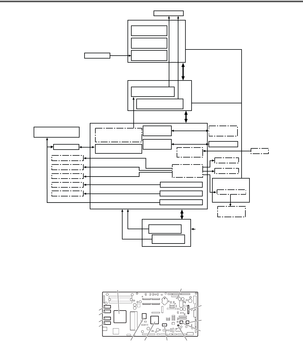
F-2-17
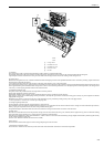
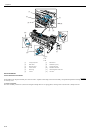
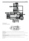
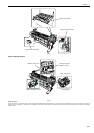
2.4.2 Main Controller
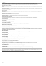
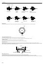
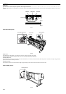
2.4.2.1 Main controller components
0014-8872
F-2-18
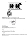
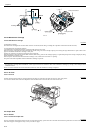
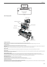
a) ASIC(IC1,IC2)
The ASIC(IC1/IC2) with a 32/16-bit internal bus is driven in sync with the 132/66 MHz external clock. It supports the following functions:
Image processing unit
This unit converts the RGB multi-bit image data or CMYK multi-bit data received from the host computer through the interface connector to the binary image data
for the ink colors used.
DMA controller
This controller controls the input interfaces such as the USB and expansion card slot as well as DMA transfer of the data to be stored in the DIMM.
Image data generation/output function
This function generates image data for color printing from the received image data and the mask pattern (corresponding to print mode) stored in the DIMM, and
store the generated image data in another DIMM. It also outputs the generated image data to the carriage relay PCB.
Interrupt controller
This controller receives and processes internal interrupts and external interrupts from the USB, image processing unit, and expansion card slot.
Timer function
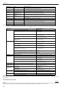
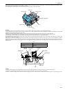
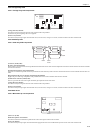
Power supply
+5.1V generation
+32V generation
Printhead
Head relay PCB
Temperature
read control
DI Sensor
read control
Multi sensor
control
Sensors
Feed motor
AC inlet
Fans control
Solenoids control
Motor control
Sensor
detection
Image data control
Remaining ink
detection
Maincontroller
Ink tank
Solenoids
Fans
Valve motor
Purge motor
Carriage motor
Carriagerelay PCB
Printhead drive
power generation
Image data
demodulating
Interface
control
Operation panel
control
Host computer
Operation panel
Maintenance cartridge
relay PCB
EEPROM control
Multi sensor
Lift motor
Media take-up PCB
Motor control
Media take-up
motor
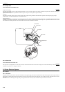
IC604
IC603
IC602
IC601
IC2IC701 IC3100 IC802
IC2900
IC2802
IC3203
IC3900
IC1