The H838 video hubs distribute antenna or cable signals to up to eight
televisions. The hubs provide two inputs to
create new channels and have built-in IR engines to
support5VIRtargets.
Twomodelsareavailable.
The has the isolation
required by the FCC for any
system thathas modulators and
anantenna.
The has a 5-42MHz
reverse channel to support
bidirectional cable systems
(cable modems, pay-per-view
andinteractivecable).
H838HHR
H838BID
video modulator
ChannelPlus Video Hubs
1
2
3
1) Hook from the top
2) Swing into place
3) push button to lock
OpenHouse modules attach from the top
tm
ChannelPlus model H616
Telephone Master Hub (4 lines x 6 phones)
Telephone Master Hub (4 lines x 6 phones)
TelephonesTelephones
From
Telco
From
Telco
RJ31XRJ31X
OutOut
Expansion
Ports
Expansion
Ports
R
T
R
T
4
R
T
R
T
3
R
T
R
T
2
R
T
R
T
1
T
e
l
e
v
i
s
i
o
n
s
C
A
T
V
ChannelPlus model H838HHR
Video Hub (3 inputs x 8 televisions)
+
1
2
v
d
c
G
n
d
I
R
M
o
du
lators
A
B
+
P
w
r
B
i
-
D
ir
e
c
t
i
o
n
a
l
A
m
p
w
/
IR
E
n
g
in
e
f
o
r
P
a
y
-
P
e
r
-V
i
e
w
&
C
a
b
l
e
M
o
d
e
m
s
Televisions
+12vdc
Gnd
IR
Modulators
CATV
/Ant
A
B
+Pwr
High Headroom Amp w/IREngine
350-086 power
supply (included)
Adaptor (included)
LED glows when
power is applied
Up to 8 televisions
RG-6 Coaxial cable
DVD, VCR, or Satellite
Modulator
Typical Installation
Antenna or cable
(H838HHR)
Cable only
(H838BID)
Televisions
+12vdc
Gnd
IR
Modulators
CATV
/Ant
A
B
+Pwr
High Headroom Amp w/IREngine
ChannelPlus
H542, H544,
H562, or H564
modulator
IR repeating system
Model H933
IR target
The H838 hub work like a zero-loss splitter. The signals
you put on the antenna/CATV input will appear on the
outputs with about 3dB of gain. Modulator inputs will
automatically appear on the outputs at an FCC legal level.
Typical remote control
Model H973
IR emitter
To control your video devices, add a modulator with IR repeating, an IR target and
an IR emitter. Point a remote control at the target in the bedroom and IR pulses
are repeated by the emitter, controlling the DVD player in the den.
Any or all of the television ports may have targets connected.
Televisions
+12vdc
Gnd
IR
Modulators
CATV
/Ant
A
B
+Pwr
High Headroom Amp w/IR Engine
FCC Requirements:
THIS PRODUCT COMPLIES WITH FCC REQUIREMENTS.
A SYSTEM USING THIS DEVICE WILL COMPLY WITH FCC REQUIREMENTS.
USE ONLY VIDEO MODULATORS THAT COMPLY WITH PART 15
OF THE FCC RULES AND HAVE 25dBmV MAX OUTPUT LEVELS. FAILURE TO
DO SO MAY VOID THE USER’S AUTHORITY TO OPERATE THIS EQUIPMENT.
THE H838HHR IS SUITABLE FOR USE WITH AN ANTENNA OR WITH
CATV SYSTEMS.
THE H838BID IS SUITABLE FOR USE WITH CATV SYSTEMS.
Things To Watch For:
Herringbone interference on modulator channel (diagonal lines):
Herringbone interference on many channels, including modulator channels (disappears
when you remove the CATV/antenna feed)
You may have chosen a
channel number that is not completely vacant. Distant UHF stations may not be watchable, but
will cause interference if you try to create a new channel at the same frequency. Also, cable
companies often have extra signals where there should be none. Try moving the modulator
channel to another number. You may have to add a low pass filter to remove the cable company
noise. If the filter does not work, try adding a DC-block to remove common mode interference.
: The RF amplifier can be overloaded by
abnormally strong signals. Often, you can cure the problem with a simple attenuator. Use a
variable attenuator and try to find a signal level where the interference just disappears.
Sometimes, the problem is one station is far stronger than the rest. In this case, attenuating all
of the signals with a simple attenuator may cause the desired stations to be weak (snowy). You
must reduce the strength of the only offending station. A common FM trap will help if the
problem is a nearby FM tower. If the problem is a nearby TV station, often the station
management can provide suitable filters.
Televisions
+12vdc
Gnd
IR
Modulators
CATV
/Ant
A
B
+Pwr
High Headroom Amp w/IR Engine
Televisions
+12vdc
Gnd
IR
Modulators
CATV
/Ant
A
B
+Pwr
High Headroom Amp w/IR Engine
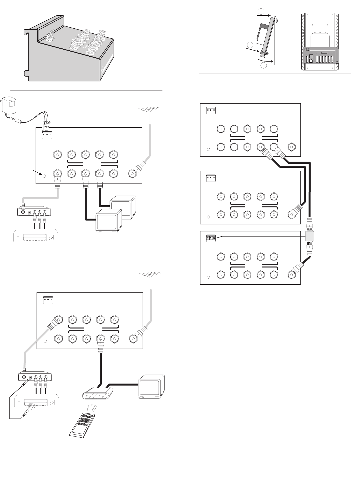
Master H838
Slave H838
Slave H838
You may connect as many as 8 more H838s to the outputs of a master H838 for a
total of 64 television outlets. The longest recommended coax run should not
exceed 150’. (That is a total of the coax from master to slave and from slave to TV.)
Specifications: typical @ 25°C ± 5° C
Gain:
CATV/Ant input to TV output
Modulator input to TV output
TV output to CATV/Ant input na -15dB
(5-42MHZ reverse channel)
Isolation
Modulator input to CATV/Ant >80dB >35dB
Bandwidth
Max CATV/Antenna input 20dBmV 20dBmV
(64 channels)
Power supply (370-086 included)
H838HHR H838BID
3dB 3dB
-10dB -10dB
Forward 5-806MHz 54-806MHz
Reverse na 5-42MHz
15 VDC @ 300mA 15 VDC @ 300mA
Expanding the modulator inputs
Add a model H881 active combiner and a single modulator input becomes eight.
Expanding the television outputs
Model H838HHR shown
IR information is only
available on port B
ChannelPlus model
2181 allows the H838
to expand IR control
also. Use one 2181 for
each slave H838.
Connect modulators
to A or B inputs


