Be sure the emitter is attached directly over the
component’s IR receiver. To locate the IR receiver, shine a
flashlight into the unit and look for the sensor.
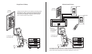
How IR repeating works
Voltage requirements:
IR Freq. range supported:
IR pickup range:
Mounting requirements:
Color:
8-12VDC
30 kHz - 60 kHz
40 ft. @ 38kHz, 25 ft. @ 56kHz
Single-gang box or ring
White
Specifications subject to change without notice.
CHANNEL VISION
Limited Warranty
Channel Vision Technology will repair or replace any defect in material or
workmanshipwhichoccursduringnormaluseofthisproductwithneworrebuilt
parts,freeof chargeintheUSA,for twoyearsfrom thedateof originalpurchase.
Thisis ano hassle warrantywith nomail in warrantycard needed.Thiswarranty
does not cover damages in shipment, failures caused by other products not
supplied by Channel Vision Technology, or failures due to accident, misuse,
abuse, or alteration of the equipment. This warranty is extended only to the
original purchaser, and a purchase receipt, invoice, or other proof of original
purchasedatewillberequiredbeforewarrantyrepairsareprovided.
Mail inservice can be obtained during the warranty period by calling (800)840-
0288toll free.AReturnAuthorization number mustbe obtainedin advance and
canbemarkedontheoutsideoftheshippingcarton.
This warranty gives you specific legal rights and you may have other rights
(whichvaryfromstatetostate).Ifaproblemwiththisproductdevelopsduringor
afterthewarrantyperiod,pleasecontactChannelVisionTechnology,yourdealer
oranyfactory-authorizedservicecenter.
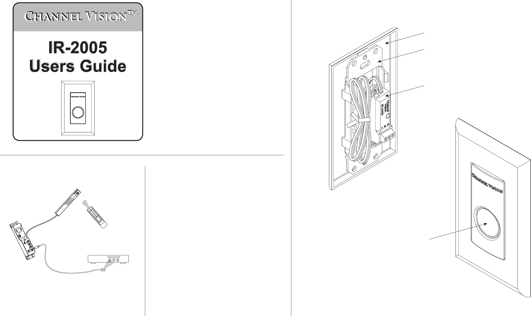
The IR-2005 includes these items:
500-181 revA
Screwless decorator style trim ring
Single-gang decorator style IR wall plate
IR-2400 Plasma proof IR receiver
IR receiver window
IR-2005
(rear view)
IR-2005
(front view)
Features:
!
!
!
Plasma Proof IR receiver
Status LEDs for IR signal indication
Mounts in a single-gang box or low-voltage ring
Specifications (typical)
T
x
B
a
t
t
R
e
w
<
<
P
l
a
y
>
F
F
>
>
L
e
a
r
n
S
t
o
p
P
a
u
s
e
1
2
3
4
5
6
7
8
9
0
P
o
w
e
r
-
/-
-
C
h
Vo
l
L
e
a
r
n
E
r
r
o
r
A
l
l
O
f
f
O
f
f
S
e
l
e
c
t
Tu
n
e
r
C
D
S
a
t
V
C
R
D
V
D
T
V
Point an
IR remote control
at the IR receiver
The IR receiver is wired to
the IR hub which routes the
signal to IR emitters
CD player
And the emitter
repeats the IR signal
in the other room.
IR Receiver
Model
P-1205
Pw
r
E
xp
an
sio
n
G
lo
bal
Zo
n
e
Z
o
n
e
G
lo
b
a
l
Emitters
+
1
2
D
C
2
5
0
m
A
IR
R
e
c
e
i
v
e
r
C
V
HANNEL
ISION
T
M