12-14
Cisco ONS 15454 Reference Manual, R7.0
78-17191-01
Chapter 12 SONET Topologies and Upgrades
12.3 12.3.1 BLSR DRI
• Both a service selector and a path selector
• Both a line switch and a path switch of a service selector
For example, if a path protection DRI service selector switch does not restore traffic, then the path
selector switches after the hold-off time. The path protection DRI hold-off timer default is 100 ms. You
can change this setting in the UPSR Selectors tab of the Edit Circuits window. For BLSR DRI, if line
switching does not restore traffic, then the service selector switches. The hold-off time delays the
recovery provided by the service selector. The BLSR DRI default hold-off time is 100 ms, but it can be
changed.
12.3.1 BLSR DRI
Unlike BLSR automatic protection switching (APS) protocol, BLSR-DRI is a path-level protection
protocol at the circuit level. Drop-and-continue BLSR-DRI requires a service selector in the primary
node for each circuit routing to the other ring. Service selectors monitor signal conditions from dual feed
sources and select the one that has the best signal quality. Same-side routing drops the traffic at primary
nodes set up on the same side of the connected rings, and opposite-side routing drops the traffic at
primary nodes set up on the opposite sides of the connected rings. For BLSR-DRI, primary and
secondary nodes cannot be the circuit source or destination.
Note A DRI circuit cannot be created if an intermediate node exists on the interconnecting link. However, an
intermediate node can be added on the interconnecting link after the DRI circuit is created.
DRI protection circuits act as protection channel access (PCA) circuits. In CTC, you set up DRI
protection circuits by selecting the PCA option when setting up primary and secondary nodes during DRI
circuit creation.
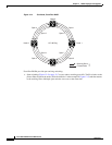
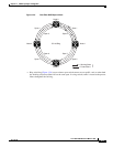
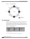
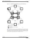
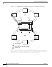
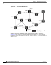
Figure 12-13 shows ONS 15454 nodes in a traditional BLSR-DRI topology with same-side routing. In
Ring 1, Nodes 3 and 4 are the interconnect nodes, and in Ring 2, Nodes 8 and 9 are the interconnect
nodes. Duplicate signals are sent between Node 4 (Ring 1) and Node 9 (Ring 2), and between Node 3
(Ring 1) and Node 8 (Ring 2). The primary nodes (Nodes 4 and 9) are on the same side, and the
secondary nodes (Nodes 3 and 8) provide an alternative route. In Ring 1, traffic at Node 4 is dropped (to
Node 9) and continued (to Node 3). Similarly, at Node 9, traffic is dropped (to Node 4) and continued
(to Node 8).


