1-16
Catalyst 2960-S Switch Hardware Installation Guide
OL-19732-04
Chapter 1 Product Overview
Front Panel
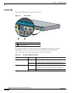
Console LEDs
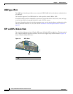
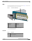
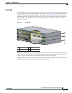
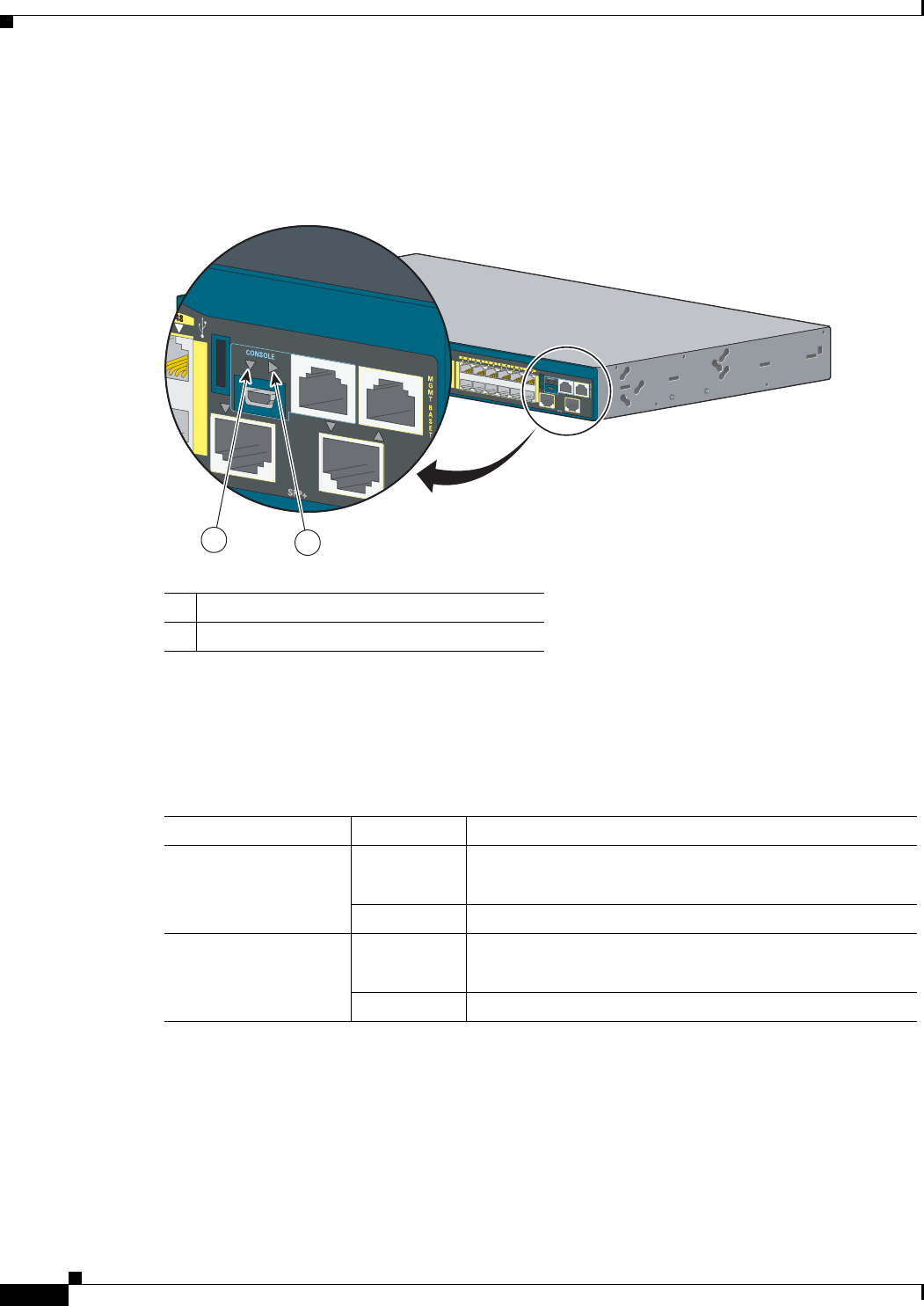
The console LEDs show which console port is in use.
Figure 1-9 Console LEDs
If you connect a cable to a console port, the switch automatically uses that port for console
communication. If you connect two console cables, the USB console port has priority.
Table 1-10 lists the console and USB port LED colors and their meanings.
1 USB console LED
2 RJ-45 console LED
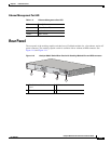
Catalyst 2960-S
Series
PoE+ 10G
11X
2X
1X
23X
24X
25X
26X
1
2
47X
48X
POWER
OVER
ETHERNET 740W
206697
Catalyst 2960-S
Series
PoE+ 10G
1
2
47X
48X
2
1
Ta b l e 1-10 RJ-45 and USB Console LEDs
LED Color Description
RJ-45 console port Green RJ-45 console port is active.
When this LED is on, the USB console port LED is off.
Off The port is not active, and the USB console port is active.
USB console port Green USB console port is active.
When this LED is on, the RJ-45 console port LED is off.
Off The port is not active, and the RJ-45 console port is active.


