


2-2
Installation and Upgrade Guide for Cisco Unified Videoconferencing 3515 MCU Release 5.6
OL-17012-01
Chapter 2 Setting Up Your Cisco Unified Videoconferencing 3515 MCU
Verifying the Package Contents
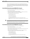
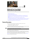
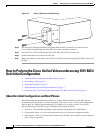
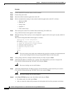
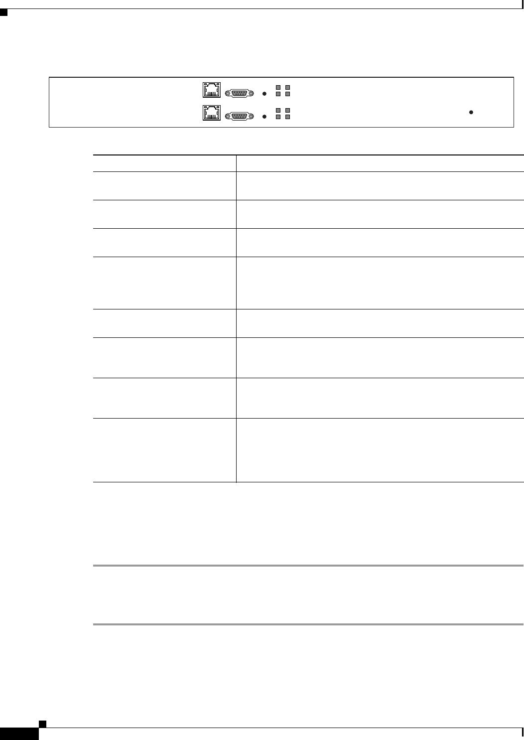
Figure 2-1 Cisco Unified Videoconferencing 3515 MCU Front Panel
Verifying the Package Contents
Procedure
Step 1 Inspect the contents of the box for shipping damage.
Step 2 Report any damage or missing items to your Cisco representative.
Step 3 Verify the package contents for the Cisco Unified Videoconferencing 3515 MCU unit. See Table 2-2.
Ta b l e 2-1 Front Panel Components
Component Description
10/100 BaseT connector An RJ-45 connector that provides the primary Ethernet connection
for the IP network port.
Serial connector A DB-9 connector that allows you to connect a PC terminal for local
configuration.
RST button Allows you to reset the Cisco Unified
Videoconferencing
3515 MCU unit manually.
GK Reg and MC LEDs Lights green when the Cisco Unified
Videoconferencing
3515 MCU is registered with a gatekeeper, or
when there is no gatekeeper registered and the auto attendant feature
is enabled.
CPU High LED Lights green when more than 50% of the Cisco Unified
Videoconferencing
3515 MCU unit resources are in use.
ACT LED Lights green to indicate that there is at least one currently active
conference on the Cisco
Unified Videoconferencing 3515 MCU
unit.
ALARM LED Lights green to indicate that an error has occurred and the
Cisco
Unified Videoconferencing 3515 MCU unit requires
resetting.
10/100 BaseT LEDs The top part of the 10/100 BaseT connector contains two LED
indicators. The left-hand LED lights green when the local IP
network link is active. The right-hand LED lights green if the
connection speed is 100 Mbps, and is off when the connection speed
is 10
Mbps.
10/100 Base T
SERIAL
RST
ACTALARM
CPU HightGK Reg
157265
10/100 Base T
SERIAL
RST
ACTALARM
CPU HightMC
PWR