


20
Installing the Cisco Content Engine 510 and 565
78-14731-02
Checking the LEDs
Step 3 Connect the other end of the power cord to a power source at your installation site.
Step 4 Power up all externally connected devices.
Step 5 Press the power control button on the front of the Content Engine.
The system should begin booting. Once the operating system boots, you are ready to initialize the basic
software configuration. (Refer to the software configuration guide or user guide that shipped with your
system.)
Note While the Content Engine is powering up, the green power LED (labeled 4 in Figure 11) is on.
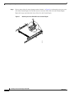
Note You can install a circular disk over the power control button to prevent accidental manual power down.
This disk, known as the power control button shield, comes with your Content Engine.
Checking the LEDs
When the Content Engine is up and running, observe the front and back panel LEDs to verify that your
system is operating properly.
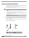
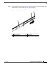
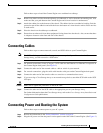
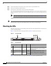
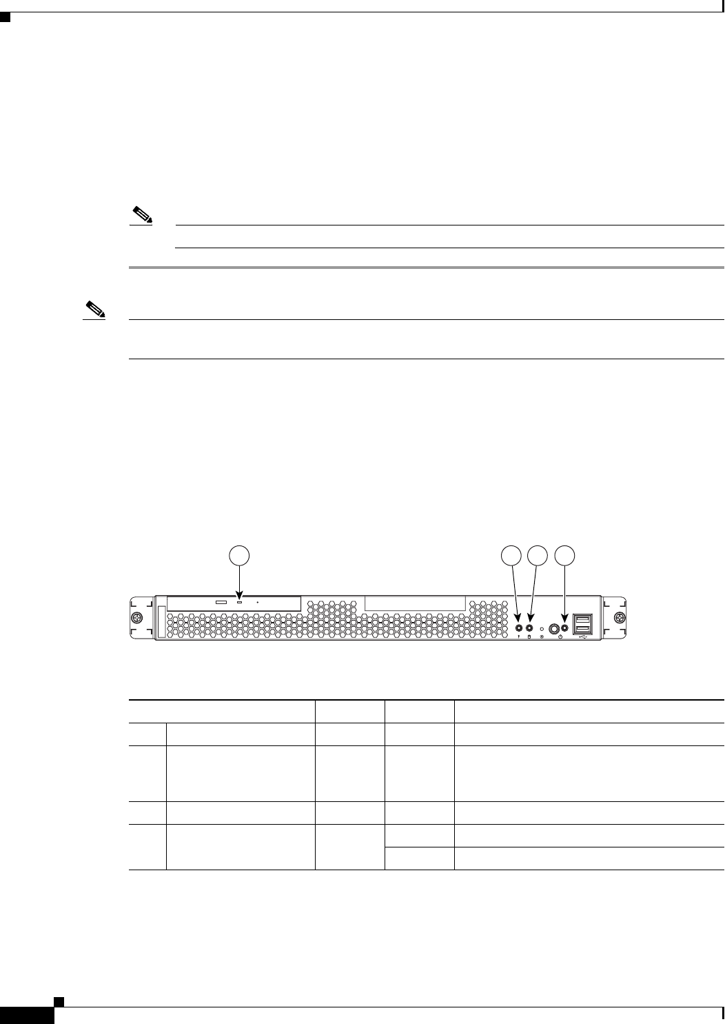
Figure 11 shows the location of front panel LEDs, and Table 2 describes their function.
Figure 11 Front Panel LEDs
Figure 12 shows the location of back panel LEDs, and Table 3 describes the LED functions.
Table 2 Front Panel LEDs
Indicator Color State Description
1 CD-ROM drive activity Green On The CD-ROM drive is in use.
2 System error Amber On A system error has occurred. An LED on the
diagnostic LED panel is also on to further
isolate the error.
3 Hard disk drive activity Green Flashing The associated hard disk drive is in use.
4 Power Green On Power is flowing to the Content Engine.
Flashing The Content Engine is in standby mode.
83109
1 32 4