


Corporate Headquarters
Cisco Systems, Inc.
170 West Tasman Drive
San Jose, CA 95134-1706
USA
http://www.cisco.com
Tel: 408 526-4000
800 553-NETS (6387)
Fax: 408 526-4100
Copyright © 2004 Cisco Systems, Inc. All rights reserved. Cisco, Cisco IOS, Cisco Systems, and
the Cisco Systems logo are registered trademarks of Cisco Systems, Inc. or its affiliates in the
United States and certain other countries. All other brands, names, or trademarks mentioned in
this document or Website are the property of their respective owners. The use of the word partner
does not imply a partnership relationship between Cisco and any other company. (0401R)
Printed in the USA on recycled paper
containing 10% postconsumer waste.
78-16710-01
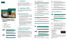
Quick Start Guide
Cisco Performance Routing
Engine (ESR-PRE2) Upgrade
Installation
1 Description
2 Upgrading to a PRE2
3 Troubleshooting
4 Technical Specifications
5 Related Documentation
Warning
Only trained and qualified
personnel should be allowed to
install, replace, or service this
equipment.
Statement 1030
Caution Always wear a grounding wrist
strap to avoid ESD damage to the
module.
1 Description
The Cisco Performance Routing Engine
(ESR-PRE2) is a single-slot module that performs
Layer 2 and Layer 3 packet routing and
forwarding using Parallel eXpress Forwarding
(PXF).
2 Upgrading to a PRE2
This upgrade should be performed by a qualified
engineer who is familiar with the Cisco router
console interface.
Upgrade Considerations
• This is a service-impacting hardware upgrade.
The router will not be available for user traffic
during the upgrade, and traffic cannot resume
until the upgrade is complete.
• PREs or PRE1s cannot operate with a PRE2 in
the same chassis and should never be installed
in a chassis together.
• PRE2 modules to be installed must have the
helper image (eboot) stored in the onboard
boot flash, no configuration, and must be set
to boot into ROMMON. Individual PRE2
modules ship in this state.
• The new PRE2 image must exist on the TFTP
server.
Saving the Startup and Running
Configuration Information
When the PRE or PRE1 is removed from the
chassis, any local configuration is lost. You must
save your configuration information to the TFTP
server or media card before removing the module.
If you plan to use the media card from your current
PRE or PRE1, you can save your startup
configuration, running configuration, and the
latest PRE2 image (from the TFTP server) to the
media card.
Saving to a Media Card
Step 1 Connect the console to the primary PRE or
PRE1.
Step 2 Copy the startup configuration and
running configuration to the existing
removable media card.
Step 3 Download the full PRE2 image from the
TFTP server to the media card.
Step 4 If you have a redundant PRE or PRE1,
save this information on the redundant
PRE or PRE1 media card.
Step 5 Remove the media cards from the modules
and set them aside.
Saving to the TFTP Server
Step 1 Connect to the primary PRE or PRE1
console.
Step 2 Save the startup configuration and
running configuration to the TFTP server.
Removing the PRE or PRE1 Module
Note Modules can be hot-swapped. However,
removing a module terminates all traffic.
We recommend that you power down the
router to ensure a successful installation.
Warning
Hazardous voltage or energy is
present on the backplane when the
system is operating. Use caution
when servicing.
Statement 1034
Step 1 Ensure that you are properly grounded.
Step 2 Power down the router
Step 3 Disconnect the cables from the PRE/PRE1.
Step 4 Unscrew the captive screws.
Step 5 Simultaneously pivot both ejector levers
away from each other to disengage the
module from the backplane.
Step 6 Slide the PRE/PRE1 out of the slot and
place it on an anti-static surface or in an
anti-static bag.
Step 7 If you are replacing a redundant
PRE/PRE1, repeat Step 3 through Step 6.
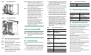
Installing a PRE2 Module
Note To ensure proper operation, always install
a single PRE2 in slot A. If you are
installing a redundant PRE2 in slot B, wait
until after you have installed and
configured the primary PRE2 in slot A.
Equipment
ESD wrist strap
Replacement PRE2 modules
Step 1 Ensure that you are properly grounded.
Step 2 Inspect the connectors on both the PRE2
and the backplane. Bent or broken pins
can cause a system malfunction.
Step 3 Carefully align the PRE2 module with the
guides in slot A in the chassis.
Step 4 Slide the module into the slot until you can
feel it seat in the backplane.