


Americas Headquarters
Cisco Systems, Inc.
170 West Tasman Drive
San Jose, CA 95134-1706
USA
http://www.cisco.com
Tel: 408 526-4000
800 553-NETS (6387)
Fax: 408 527-0883
Cisco, CiscoSystems, the Cisco logo, and the CiscoSystems logo are registered trademarks or
trademarks of CiscoSystems, Inc. and/or its affiliates in the United States and certain other countries.
All other trademarks mentioned in this document or Website are the property of their respective
owners. The use of the word partner does not imply a partnership relationship between Cisco and any
other company. (0705R)
© 2009 Cisco Systems, Inc. All rights reserved.
OL-18974-01
QUICK START GUIDE
Installing Cisco uBR-MC16U/X
and uBR-E-16U
Cable Interface Line Cards
1 Purpose
2 Feature Description
3 Prerequisites
4 Installing the Card
5 Removing the Card
6 Troubleshooting
7 Technical Specifications
8 Related Documentation
Warning
Only trained and qualified
personnel should be allowed to
install, replace, or service this
product.
Caution You must be properly grounded
before handling this
ESD-sensitive product.
1 Purpose
This quick start guide shows you how to install a
Cisco uBR-MC16 cable interface line card in the
Cisco uBR7200 series router.
2 Feature Description
The Cisco uBR-MC16 cable interface line card
improves RF performance, supports spectrum
management, increases system performance and
supports online insertion and removal (OIR).
The line card is available in three configurations:
• Cisco uBR-MC16U—With an onboard
upconverter and green end tabs
• Cisco uBR-E-16U—With an onboard
upconverter and slate blue end tabs
• Cisco uBR-MC16X—Without an onboard
upconverter and yellow end tabs
3 Prerequisites
• The Cisco NPE-400 or the Cisco NPE-G1 or
the Cisco NPE-G2 network processing engine
must be used with this card.
• If you are using the Cisco uBR-MC16 line card
to replace a different type of card, you must
reconfigure the MC16U/X/E card.
• We recommend that you reload a Cisco 7200
series router when replacing a cable interface
line card with a card of a different type.
4 Installing the Card
Note The uBR-E-16U line card is an entry-level
version of the uBR-MC16U line card, and
fits only in the uBR7225VXR chassis.
Step 1 Make sure that you are grounded.
Step 2 Use both hands to grasp the line card by its
metal carrier edges and align the line card
with the slot guides, component side up.
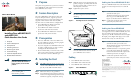
Step 3 With the metal carrier aligned in the slot
guides (see Figure 1), briskly slide the card
into the card slot until you feel it seat in
the backplane connectors.
Step 4 Tighten the captive screws.
Note The captive screws provide grounding for
the electromagnetic interference (EMI)
shielding.
Figure 1 Installing the Card in the Chassis
Note The cable interface line card insertion and
removal method is the same for all the
Cisco uBR7200 series routers.
Cabling
• Cisco uBR-MC16U—Green tabs
• Cisco uBR-E-16U—Slate blue tabs
• Cisco uBR-MC16X—Yellow tabs
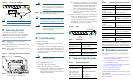
Figure 2 Cisco uBR-MC16U
95800
US1
US2
US3
US4
US5
US6
US7
D
S
0-R
F
D
S
1
-R
F
uB
R
- M
C
28
U
D
S
uBR - MCI6E
U
S
U
S
U
S
U
S
U
S
U
S
0
1
2
3
4
5
ENABLED
95801
uBR - MC16E
US0
US1
US2
US3
US4
US5
DS
ENABLED
Cabling the Cisco uBR-MC16U/E-16U
The Cisco uBR-MC16U/E-16U cable interface line
card has an onboard upconverter. To cable the
card:
Step 1 Connect the downstream cable to the
downstream (DS) port.
The RF downstream port rings and end
tabs are green for uBR-MC16U (see
Figure 2) and slate blue for uBR-E-16U.
Step 2 Connect the upstream cables to the
upstream ports (US0—US5).
Cabling the Cisco uBR-MC16X
The Cisco uBR-MC16X cable interface line card
(not supported on Cisco uBR7225VXR) does not
have an onboard upconverter. The card may
require up to 10-dB of attenuation due to a higher
IF output power (higher than legacy Cisco cable
interface line cards). To cable the card:
Step 1 Connect the downstream cable to the
downstream (DS) port on the card.
The IF downstream port ring and end tabs
are yellow. See Figure 3.
Step 2 Add RF attenuators as required to get the
correct IF output. Insert the attenuator
between the downstream IF output cable
and the upconverter. See Figure 3.
Step 3 Connect the upstream cables to the
upstream ports on the card (US0—US5).