


17
Versatile Interface Processor (VIP6-80) Installation and Configuration Guide
OL-5078-01
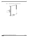
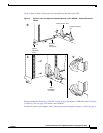
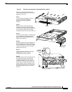
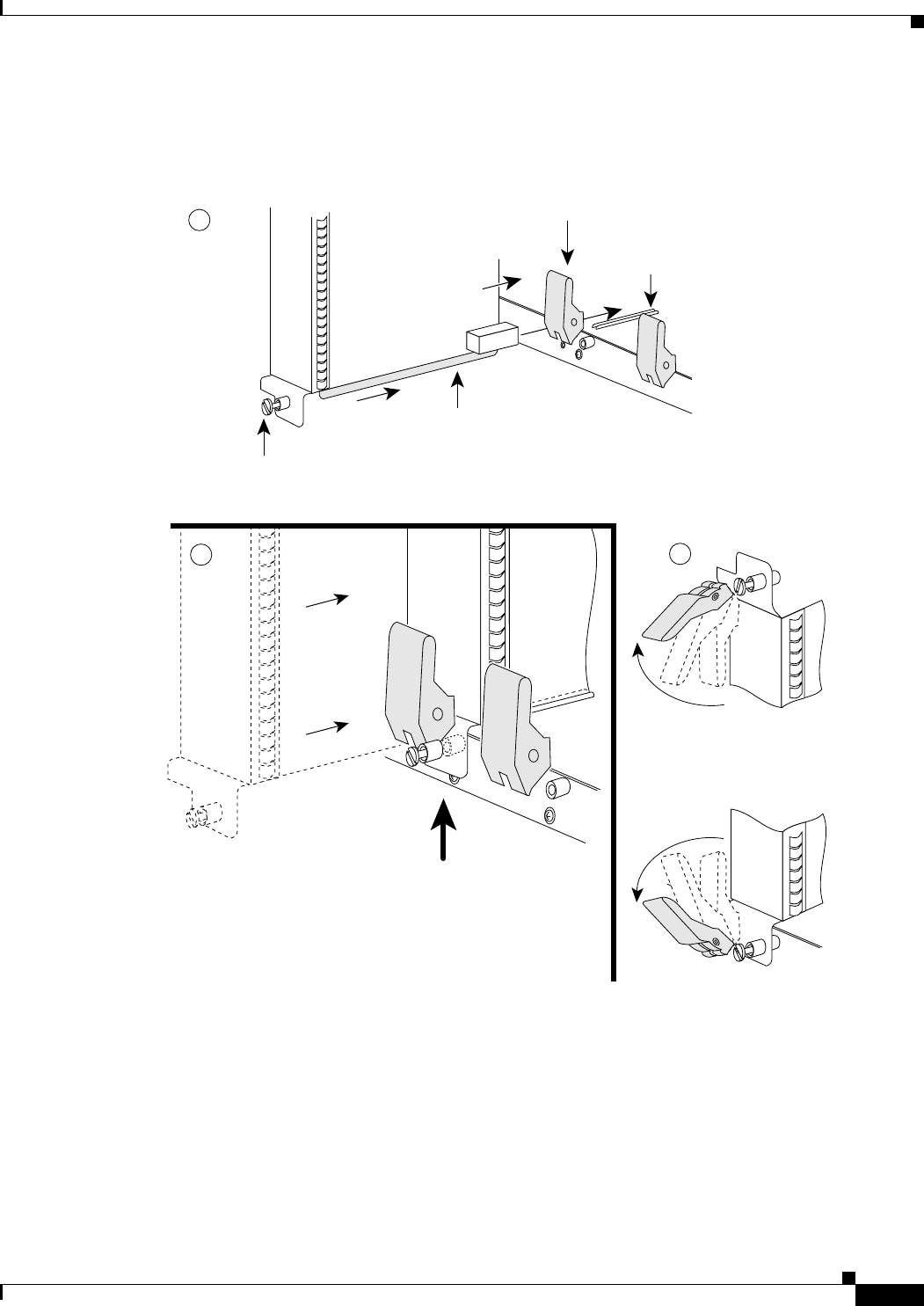
Figure 3 shows a detail of the ejector lever mechanism on the ends of the VIP.
Figure 3 Ejector Levers and Captive Installation Screws on the VIP6-80—Vertical Orientation
Shown
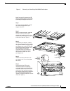
Proceed to either the “Removing a VIP6-80” section on page 18 to replace a VIP6-80 or to the “Installing
a VIP6-80” section on page 24 to install a new VIP6-80.
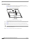
To install or remove a port adapter, see the “Removing and Installing Port Adapters” section on page 19.
H1482a
Processor module
slot
a
c
Stop
immediately
on contact
Bottom ejector lever
Captive
installation
screw
Processor
module
carrier guide
b