


18
Versatile Interface Processor (VIP6-80) Installation and Configuration Guide
OL-5078-01
Removing a VIP6-80
This section describes the procedure for removing a VIP6-80.
Caution If your router has an RSP2 as the standby with the high system availability (HSA) feature or high
availability (HA) features enabled, online insertion and removal of any interface processor in either
CyBus might cause the standby RSP2 to reboot with a bus error or a processor memory parity error. The
active RSP recovers from this event and issues a “cBus Complex Restart” message. Systems that are
configured with an RSP4/4+, an RSP8, or an RSP16 as the system standby are not affected and do not
experience this problem. For more information on HSA or HA, refer to your RSP installation and
configuration guide.
If your router has an RSP2 as the standby with the HSA feature or HA features enabled, perform the
following steps before proceeding with the VIP6-80 removal:
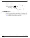
Step 1 Attach an ESD-preventive wrist strap between you and an unpainted chassis surface.
Step 2 Remove the standby RSP2.
Step 3 Wait 20 to 30 seconds. This time will vary depending on the number of interfaces installed on your
system.
This completes the additional steps you must perform if you have an RSP2 configured as the standby
with HSA or HA enabled. Continue with the following steps to finish the removal of the VIP6-80 from
the router.
Perform the following steps to remove a VIP6-80 from your router:
Step 1 Attach an ESD-preventive wrist strap between you and an unpainted chassis surface, if you have not
already done so.
Step 2 Disconnect all cables from the VIP6-80 port adapter interface ports.
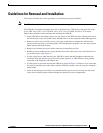
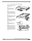
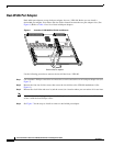
Step 3 Use a screwdriver to loosen the captive installation screws at both ends of the board. (See Figure 3a.)
Caution Always use the ejector levers to remove a VIP6-80. Failure to do so can cause erroneous system error
messages indicating a board failure.
Step 4 Place your thumbs on the ejector levers and simultaneously pull both of the ejector levers outward (in
the direction shown in Figure 3a) to release the board from the backplane connector.
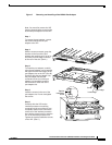
• Use the board’s handle to carefully pull it straight out of the slot, keeping your other hand under the
carrier to guide it. (See Figure 3c.) Keep the board parallel to the backplane.
• If you removed a VIP6-80 or interface processor and the interface processor slot is to remain empty,
install an interface processor filler (Product Number MAS7K-BLANK=) to keep dust out of the
router, maintain proper airflow inside the router, and ensure compliance with EMI approvals by
providing a tight EMI-preventive seal. Do not leave the interface processor slot open.