


23
Versatile Interface Processor (VIP6-80) Installation and Configuration Guide
OL-5078-01
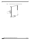
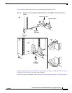
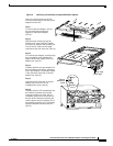
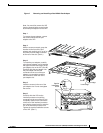
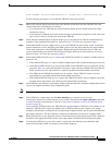
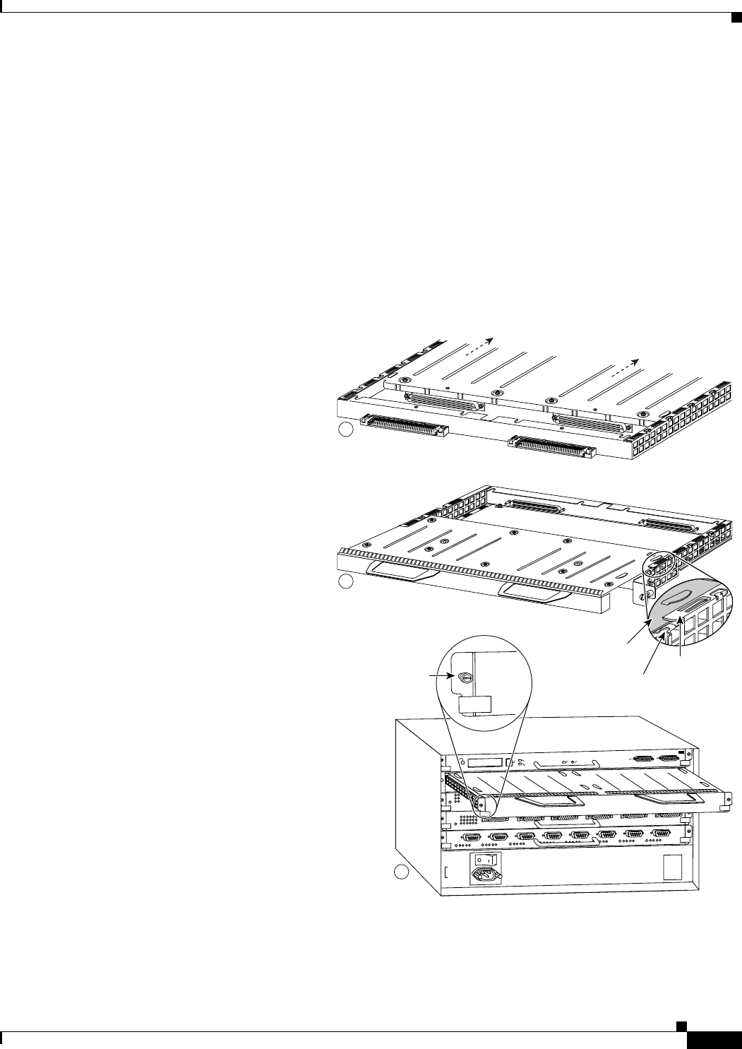
Figure 7 Removing and Installing a Dual-Width Port Adapter
Note: You must first remove the VIP
from the chassis before removing the
dual-width port adapter from the VIP.
Step 1
To remove the port adapter, remove
the screws that secure the port
adapter to the VIP.
Step 2
With the screws removed, grasp the
handles on the front of the port
adapter and carefully pull it out of its
slot, away from the edge connector
at the rear of the slot. (See A.)
27869
Step 3
To insert the port adapter, carefully
align the port adapter carrier between
the upper and the lower edges of the
port adapter slot on the VIP. (See B.)
Carefully slide the port adapter into
the port adapter slot until the
connectors at the rear of the port
adapter are completely seated in
the connectors at the rear of the
port adapter slot.
Step 4
Install the screws in the rear of the
port adapter slot. Do not overtighten
the screws.
Step 5
Carefully slide the VIP into the
interface processor slot until the
connectors at the rear of the VIP are
completely seated in the connectors
at the rear of the interface processor
slot. Use the ejector levers to seat the
VIP in the interface processor slot.
Tighten the captive installation screws
on the VIP. (See C.)
E
JE
C
T
S
LO
T
0
S
LO
T
1
N
O
R
M
A
L
C
P
U
H
A
LT
R
E
S
E
T
A
U
X
.
C
O
N
S
O
L
E
ROUTE SWITCH PROCESSOR
Captive
installation
screw
A
Upper edge
Lower edge
Carrier
B
C