


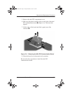
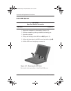
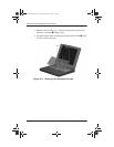

Removal and Replacement Procedures
Maintenance and Service Guide 5–3
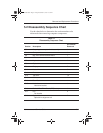
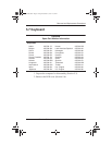
5.2 Disassembly Sequence Chart
Use the chart below to determine the section number to be
referenced when removing computer components.
Table 5-1
Disassembly Sequence Chart
Section Description
# of Screws
Removed
5.3 Preparing the computer for disassembly 0
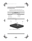
5.4 Computer feet 0
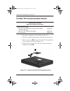
5.5 Mini PCI Communications Board 1
5.6 LED cover 0
5.7 Keyboard 2
5.8 Optical drive 1
5.9 Display 7
5.10 Heat sink 5
5.11 Processor 0
5.12 Top cover 15
5.13 Diskette drive 2
5.14 TouchPad 1
5.15 Hard drive
Hard drive bracket
3
5.16 Disk cell Real Time Clock (RTC) battery 0
5.17 Fan
Fan bracket
2
5.18 System board
Optical drive alignment rail
7
238850-003.book Page 3 Friday, December 21, 2001 2:53 PM