


4–40 Maintenance and Service Guide
Removal and replacement procedures
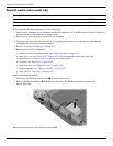
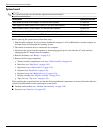
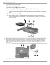
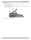
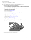
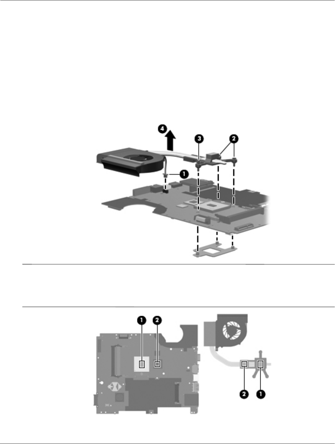
Remove the UMA fan/heat sink assembly:
1. Turn the system board upside down.
2. Disconnect the fan cable 1 from the system board.
3. Loosen the two Phillips PM2.5×11.0 captive screws 2 and the Phillips PM2.5×15.0 captive screw 3 that
secure the UMA fan/heat sink assembly to the system
board.
Ä
Loosen the screws in the order indicated on the fan/heat sink assembly to ensure consistent pressure over the processor
board.
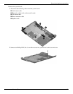
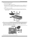
4. Remove the fan/heat sink assembly 4.
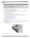
✎
Due to the adhesive quality of the thermal material located between the fan/heat sink assembly and
system board components, it may be necessary to move the fan/heat sink assembly from side to side to
detach the assembly.
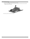
✎
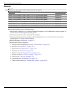
The thermal material must be thoroughly cleaned from the surfaces of the fan/heat sink assembly and the system
board each time the fan/heat sink assembly is removed. Thermal material is applied to the UMA fan/heat sink
assembly to correspond with components on the system board as follows: the processor
1
and the Northbridge
chip
2
. Replacement thermal material is included with all system board, fan/heat sink assembly, and processor
spare part kits.
Reverse this procedure to install the UMA fan/heat sink assembly.