


Removal and replacement procedures
Maintenance and Service Guide 4–35
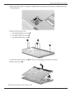
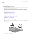
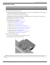
System board
✎
All system board spare part kits include UMA or discrete graphics subsystem memory, built-in modem, and
replacement thermal material.
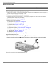
Before removing the system board, follow these steps:
1. Shut down the computer. If you are unsure whether the computer is off or in Hibernation, turn the computer on,
and then shut it down through the operating system.
2. Disconnect all external devices connected to the computer.
3. Disconnect the power from the computer by first unplugging the power cord from the AC outlet and then
unplugging the AC adapter from the computer.
4. Remove the battery (see “Battery” on page 4-6).
5. Remove the following components:
a. Optical drive (see “Optical drive” on page 4-7)
b. Hard drive (see “Hard drive” on page 4-9)
c. Keyboard (see “Keyboard” on page 4-15)
d. Keyboard cover (see “Keyboard cover” on page 4-17)
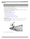
e. Power button board (see “Power button board” on page 4-19)
f. Display assembly (see “Display assembly” on page 4-20)
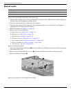
g. Top cover (see “Top cover” on page 4-26)
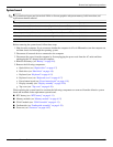
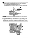
When replacing the system board, be sure that the following components are removed from the defective system
board and installed on the replacement system board:
■ RTC battery (see “RTC battery” on page 4-11)
■ Memory module (see “Memory module” on page 4-12)
■ WLAN module (see “WLAN module” on page 4-13)
■ Fan/heatsink (see “Fan/heatsink assembly” on page 4-39)
■ Processor (see “Processor” on page 4-42)
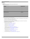
Description Spare part number
UMA system board, GM45 with built-in modem, Digital Media Slot, and HDMI port 485218-001
UMA system board, GL40 with built-in modem, Digital Media Slot, and HDMI port 485219-001
Discrete system board, PM45 with built in modem, Digital Media Slot, and HDMI port 488338-001
UMA system board, GL40 with built-in modem and Digital Media Slot 494282-001
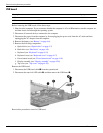
optical drive connector 489127-001