Chapter 4 System Support
Compaq iPAQ Family of Internet Devices
First Edition - March 2000
4-18
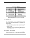
Table 4-10 lists the mapping of the configuration memory.
Table 4-10.
Configuration Memory (CMOS) Map
Table 4-10.
Configuration Memory (CMOS) Map
Location Function Location Function
00-0Dh Real-time clock 24h System board ID
0Eh Diagnostic status 25h System architecture data
0Fh System reset code 26h Auxiliary peripheral configuration
10h Diskette drive type 27h Speed control external drive
11h Reserved 28h Expanded/base mem. size, IRQ12
12h Hard drive type 29h Miscellaneous configuration
13h Security functions 2Ah Hard drive timeout
14h Equipment installed 2Bh System inactivity timeout
15h Base memory size, low byte/KB 2Ch Monitor timeout, Num Lock Cntrl
16h Base memory size, high byte/KB 2Dh Additional flags
17h Extended memory, low byte/KB 2Eh-2Fh Checksum of locations 10h-2Dh
18h Extended memory, high byte/KB 30h-31h Total extended memory tested
19h Hard drive 1, primary controller 32h Century
1Ah Hard drive 2, primary controller 33h Miscellaneous flags set by BIOS
1Bh Hard drive 1, secondary controller 34h International language
1Ch Hard drive 2, secondary controller 35h APM status flags
1Dh Enhanced hard drive support 36h ECC POST test single bit
1Eh Reserved 37h-3Fh Power-on password
1Fh Power management functions 40-FFh Feature Control/Status
NOTES:
Assume unmarked gaps are reserved.
Higher locations (>3Fh) contain information that should be accessed using the INT15, AX=E845h
BIOS function (refer to Chapter 8 for BIOS function descriptions).
4.7.1 CMOS ARCHIVE
There is no provision for clearing the contents of the configuration memory (CMOS). During
POST, a copy of the CMOS data is written to a sector of the 82802 FWH. This means that
changes to CMOS will be stored on the following boot. Should the system hang during boot as
the result of corrupted CMOS data, then a Power Button Override boot should be invoked with
the following procedure:
1.
Initiate a power cycle by pressing and releasing the Power button, then pressing and holding
the power button for about four seconds so that the system should record a power button
override event.
2.
Power down the system.
3.
Press and release the power button, initiating a boot sequence. The system should detect the
occurrence of a power button override event and will load the CMOS archive data stored in
the FWH allowing a successful boot. All passwords and settings used in the previous
successful boot would be restored.
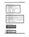
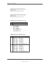
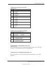
4.7.2 STANDARD CMOS LOCATIONS
The following paragraphs describe standard configuration memory locations 0Ah-3Fh. These
locations are accessible through using OUT/IN assembly language instructions using port 70/71h
or BIOS function INT15, AX=E823h.


