


5–56 Maintenance and Service Guide
Removal and Replacement Procedures
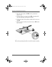
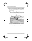
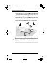
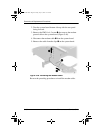
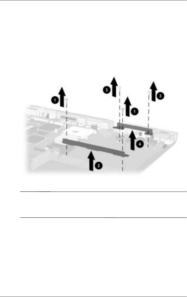
2. Remove the two TM2.5 × 5.0 screws
1
that secure the optical
drive front alignment rail to the base enclosure (Figure 5-43).
3. Remove the front alignment rail
2
from the base enclosure.
4. Remove the two TM2.5 × 5.0 screws
3
that secure the optical
drive rear alignment rail to the base enclosure.
5. Remove the rear alignment rail
4
from the base enclosure.
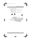
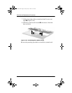
Figure 5-43. Removing the Optical Drive Alignment Rails
✎
The optical drive alignment rails are included in the
Miscellaneous Plastics/Hardware Kit, spare part number
285541-001.
279372-001.book Page 56 Friday, July 19, 2002 11:50 AM