


Removal and Replacement Procedures
Maintenance and Service Guide 5–57
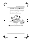
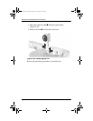
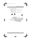
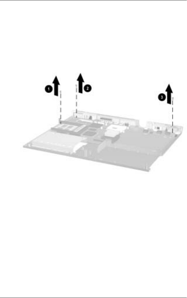
6. Remove the following screws:
❏
TM2.5 × 5.0 screw
1
next to the PC Card assembly
(Figure 5-44)
❏
TM2.5 × 5.0 screw
2
next to the RJ-11 and
RJ-45 connectors
❏
TM2.5 × 5.0 screw
3
next to the audio connectors
Figure 5-44. Removing the System Board Screws
279372-001.book Page 57 Friday, July 19, 2002 11:50 AM