


Removal and Replacement Procedures
Maintenance and Service Guide 5–57
h. Top cover, microphone, and TouchPad cable
(Section 5.20)
i. Fan (Section 5.21)
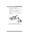
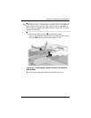
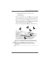
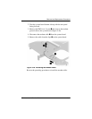
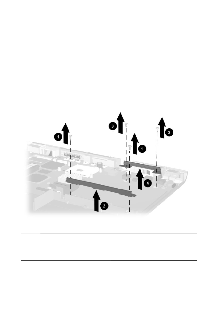
2. Remove the two TM2.5 × 5.0 screws
1
that secure the optical
drive front alignment rail to the base enclosure (Figure 5-43).
3. Remove the front alignment rail
2
from the base enclosure.
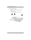
4. Remove the two TM2.5 × 5.0 screws
3
that secure the optical
drive rear alignment rail to the base enclosure.
5. Remove the rear alignment rail
4
from the base enclosure.
Figure 5-43. Removing the Optical Drive Alignment Rails
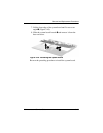
✎
The optical drive alignment rails are included in the
Miscellaneous Plastics/Hardware Kit, spare part number
285541-001.