


Removal and Replacement Procedures
Maintenance and Service Guide 5–3
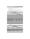
5.2 Disassembly Sequence Chart
Use the following chart to determine the section number to be
referenced when removing computer components.
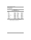
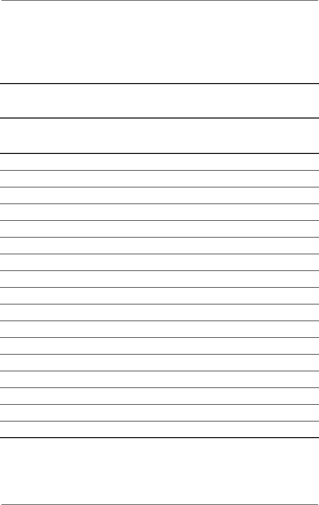
Table 5-1
Disassembly Sequence Chart
Section Description
#ofScrews
Removed
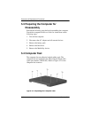
5.3 Preparing the computer for disassembly 0
5.4 Computer feet 0
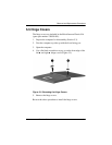
5.5 Hinge covers 0
5.6 Keyboard 2
5.7 Display 4
5.8 EMI shield 1
5.9 Top cover 18
5.10 TouchPad 5
5.11 Speakers 10
5.12 Microphone 0
5.13 Display lid switch board 1
5.14 Heat sink 5
5.15 Infrared board 1
5.16 System board 11
5.17 PC Card assembly 2
5.18 Mini PCI board 0
5.19 Disk cell real time clock (RTC) battery 0