


5–12 Maintenance and Service Guide
Removal and Replacement Procedures
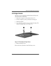
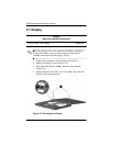
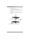
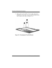
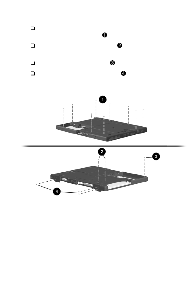
3. Remove the following screws:
Nine pewter M2.5 × 7.0 screws from the recesses in the
bottom of the computer
(Figure 5-8)
Two black M2.5 × 4.5 screws from the bottom of the
computer
One silver M2 × 5.5 screw from the battery bay
Three black M2.5 × 4.5 screws from the rear panel of
computer
Figure 5-8. Removing the Top Cover Screws