


5–30 Maintenance and Service Guide
Removal and Replacement Procedures
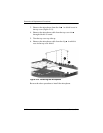
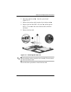
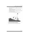
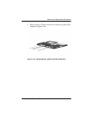
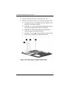
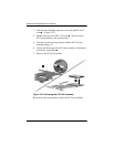
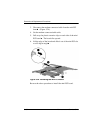
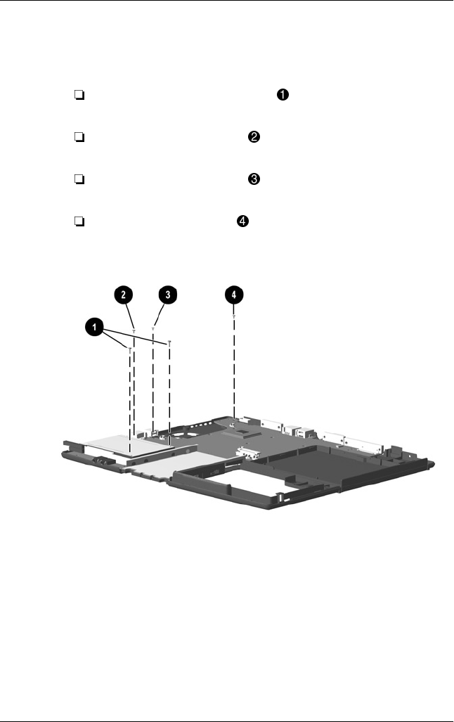
4. Position the base enclosure so the front faces you.
5. Remove the following screws, as illustrated in Figure 5-20:
two black M2 × 14.5 screws that secure the PC Card
assembly to the base enclosure
black M2.5 × 4.5 screw near the USB connector that
secures the system board to the base enclosure
black M2.5 × 4.0 screw that secures the modem
connector/cable to the base enclosure
blackM2×4.0screw near the display connector that
secures the system board to the base enclosure
Figure 5-20. Removing the System Board Screws