


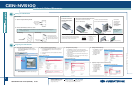

MOUNTING
A. Attach the Supplied Mounting Bracket.
B. Mount the CEN-NVS100 to a Wall or to a Rack.
CEN-NVS100
CEN-NVS100
Network Video Streamer
1
©2009 Specifications subject to
change without notice.
ediug tratskciuq
www.crestron.com
888.273.7876 201.767.3400
QUICKSTART DOC. 6746A (2022586) 03.09
(4) Drywall Screws,
(Not Supplied)
Installing the CEN-NVS100
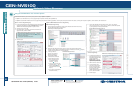
Configuring the CEN-NVS100
NOTE: The CEN-NVS100 must be installed in a temperature-controlled environment ranging from
32° to 104° F (0° to 40° C).
Wall Mounting: Rack Mounting:
Rack Mount Screws
(Not Supplied)
Mount the left or right side
of the bracket to the front or
rear rail of a rack (mounting of
right side of bracket is shown).
CONNECTIONS
P = (For factory use only)
C = Common
I = Digital Input
O = Digital Output
+ = RS-485, T+/R+
– = RS-485, T-/R-
12V DIO 485
P C I O +
–
(Front) Video Connection
If necessary, use the supplied
BNC-to-RCA adapter to connect
to the camera.
(Rear, Optional) 6-pin Terminal Block Connection
Using the supplied terminal block mating connector,
connect the 6-pin terminal block to external devices
such as an alarm, sensor, and PTZ camera.
NOTE: By default,
the CEN-NVS100
uses DHCP.
Connection to
Third-Party PoE
Power Source.
For installation
information, refer to
the third-party device
documentation.
(For Factory Use Only)
Connection to Crestron PoE Switch
(Part No. CEN-SW-POE-5 Shown)
(Rear) Power over Ethernet (PoE) Connection
Connection to Crestron
®
PoE Injector
(Part No. PWE-4803RU)
For Future or Factory Use Only
(For Future Use)
1
2
A. Access the Configuration Web Pages.
1. In the Device Discovery Tool of Crestron Toolbox™,
select Crestron CEN-NVS100. The home page of the
CEN-NVS100 opens.
2. Select Configuration. The “System” configuration page
opens (refer to Step B).
CEN-NVS100 Home Page (Default)
D. Configure Network Settings.
1. Click Network. The “Network”
configuration page opens.
2. Configure a static IP
address and related
network information.
3. Click Save.
“System” Configuration Page
B. (Optional) Configure System Settings.
1. On the “System” configuration page, modify the default host
name, CEN-NVS100, using a name that is meaningful for
your environment.
2. Configure DI (Digital Input) and DO (Digital Output) settings.
3. Click Save.
C. Configure Security Settings.
1. Click Security. The “Security” configuration page opens.
2. In the Root Password pane, assign an administrator password
and then click Save at the bottom of the pane. A log-in
window appears.
3. Enter root as the user name, and then enter the password you
entered in step 2.
4. In the Add User pane, create a user account whose user type
is set to Viewer, and then click Add.
“Security” Configuration Page
“Network” Configuration Page
E. (Optional) Configure Camera Control Settings.
1. Click Camera Control.
The “Camera Control”
configuration page opens.
2. Click PTZ Camera,
and then configure
the camera settings
as required.
3. Click Save.
“Camera Control” Configuration Page
(4) Screws, M3 x 5mm
Phillips Flat Head
(Supplied)
Mounting Bracket
All brand names, product names and trademarks
are the property of their respective owners.