


AVAILABLE ACCESSORIES
CNLPS-120 Power Supply for CNLGE-8, 120V
CNLPS-277 Power Supply for CNLGE-8, 277V
Specifications for CNLPS (Sold Separately)
Load Ratings
24 Volts AC, 50 VA
For use with CNLGE-8 modules only
Maximum Load: (6) modules
Power Requirements
CNLPS-120: 120 Volts AC, 50/60Hz, single-phase
CNLPS-277: 277 Volts AC, 50/60Hz, single-phase
Connectors
120 VAC: (1) 2-position captive screw terminal, line power input (CNLPS-120 only)
277 VAC: (1) 2-position captive screw terminal, line power input (CNLPS-277 only)
COMMON: (5) Captive screw terminals, output common buss
24VAC: (5) Captive screw terminals, 24 Volt AC output buss
Fuse: CNLPS-120: (1) 3AG, 1 Amp, time-lag; CNLPS-277: (1) FLQ 0.5 Amp
Environmental
Temperature: 32° to 104°F (0° to 40°C)
Humidity: 10% to 90% RH (non-condensing)
Enclosure
Occupies 1 module space in a CLC-6 cabinet
(Contact factory for applications requiring CSTC cabinet)
www.crestron.com
|
800.237.2041
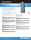
The CNLGE-8 module provides 8 channels of switching for non-dimmable lighting
and power loads. Each channel features an isolated SPST mechanically latched
relay, which maintains its state even if power is disrupted. The CNLGE-8 occupies a
single module space in any CSTC or CLC-6 cabinet (not including required CNLPS
power supply), and is designed to communicate with the PAC2 control system, or
any Crestron control system, via the Cresnet control network.
> 8 channels of switching for non-dimmable loads
> Mechanically-latched, isolated, single-pole / single-throw relays
> Each switched circuit maintains its state in case of power failure
> Occupies 1 module space in a CSTC lighting cabinet
> Requires CNLPS power supply
> Controlled by PAC2 or PAC2M automation control system
SPECIFICATIONS
Load Ratings
Relay Closure: 20A @ 125V AC (Tungsten); 20A @ 277V AC (Resistive or Fluorescent
Ballast); 0.5 HP @ 110-125V AC; 1.5 HP @ 220-277V AC;
Note: May not be compatible with some high inrush current loads
Power Requirements
24 Volts AC; requires one CNLPS power supply for every (6) CNLGE-8 modules
Connectors
1 - 8: (8) 2-position captive screw terminals, isolated Class 1 SPST relay switch circuits
Split-coil, mechanically-latching SPST relay closure
NET: (1) 4-pin 5mm detachable terminal block, Cresnet slave port
Connects to Cresnet control network
24VAC: Attached 2-conductor Class 2 cable, relay power input
Connects to CNLPS power supply (sold separately)
Controls
ID CODE: (2) Rotary DIP Switches, set Cresnet ID
LED Indicators
POWER: Indicates DC power supplied from Cresnet network
ACTIVITY: Indicates communication with Cresnet system
1 – 8: Indicate when each relay is closed
Environmental
Temperature: 32° to 104°F (0° to 40°C)
Humidity: 10% to 90% RH (non-condensing)
Enclosure
Occupies 1 module space in a CLC-6 cabinet
(Contact factory for applications requiring CSTC cabinet)
Specifications subject to change without notice. Doc.4831 12/07
©2007 Crestron Electronics, Inc. All brand names, product names and trademarks are the property of their respective owners.
Crestron Electronics, Inc.
15 Volvo Drive
l
Rockleigh, NJ 07647
Tel: 800.237.2041 / 201.767.3400
l
Fax: 201.767.1903
Crestron CNLGE-8
8 Channel Switch Module