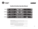
Operation Manual
CT Power Amplifiers
page 4
Important Safety Instructions ...................................... 2
Declaration of Conformity ...........................................3
1 Welcome .........................................5
1.1 Features ........................................................... 5
2 How to Use This Manual ........................5
3 Features ........................................... 5
4 Setup .............................................. 6
4.1 Unpack Your Amplifier ...................................... 6
4.2 Install Your Amplifier ........................................6
4.3 Ensure Proper Cooling .....................................6
4.4 Choose Input Wire and Connectors .................. 7
4.5 Choose Output Wire and Connectors ...............7
4.6 Wire Your System .............................................8
4.7 Connect to AC Mains .......................................8
4.8 Startup Procedure ............................................ 9
5 Precautions ......................................9
6 Front Panel ....................................... 10
7 Back Panel ........................................11
8 Amp Configuration ...............................12
8.1. 70Hz HPF (High Pass Filter) .............................12
8.2 Limiter .............................................................12
9 Operating Modes .................................12
9.1 Normal ..............................................................12
9.2 Green Power ..................................................... 12
9.3 Deep Sleep .......................................................12
10 Auxiliary Ports .................................13
9.1 Deep Sleep .......................................................13
9.2 Amp Status ....................................................... 13
11 Input Routing ...................................13
13 Advanced Features ............................14
13.1 Protection Systems ......................................... 14
13.1.1 Thermal Indicator ....................................14
13.1.2 Fault .......................................................14
13.1.3 High-Pass Filters .................................... 14
13.1.4 AC Under/Over Voltage Protection ..........14
13.1.5 Circuit Breaker ........................................ 14
13.1.6 Convection-cooled Chassis .................... 14
13.1.7 Auto-Standby ..........................................14
13.2 Features ..........................................................14
13.2.1 Switching Power Supply ........................14
13.2.2 Power Mode ............................................14
13.2.3 Adaptive Voltage Rail ..............................14
13.2.4 DriveCore Power Stage ...........................14
14 Accessories .....................................14
14.1 XFMR 4/8 ..................................................14
14.2. Rack Support/Ears ....................................14
15 Troubleshooting ................................15
15.1 Power Indicator ...............................................15
15.2 Fault Indicator .................................................15
15.3 Thermal Indicator ............................................15
15.4 Clip Indicator .................................................. 15
15.5 Signal Indicator ..............................................15
15.6 Ready Indicator ............................................... 15
16 Specifications ................................... 16
17 AC Power Draw and Thermal Dissipation ...17
18 Service ...........................................21
19 Warranty ......................................... 22
Product Registration Form ...........................................25
Factory Service Information Form ............................... 27
Table of Contents


