


eu.cyberpowersystems.com
Professional Rack Mount UPS
1500VA/2200VA
User Manual
K01-1500E0C-02
SAFETY WARNINGS
(SAVE THESE INSTRUCTIONS)
This manual contains important safety instructions. Please read and follow all instructions carefully
during installation and operation of the unit. Read this manual thoroughly before attempting to
unpack, install, or operate your UPS.
This equipment can be operated by any individuals with no previous training.
The socket-outlet shall be installed near the equipment and easily accessible.
During the installation of this equipment it should be assured that the sum of the leakage currents of
the UPS and the connected loads does not exceed 3.5mA.
Attention, hazardous through electric shock. Also with disconnection of this unit from the mains,
hazardous voltage still may be accessible through supply from battery. The battery supply should be
therefore disconnected in the plus and minus pole at the quick connectors of the battery when
maintenance or service work inside the UPS is necessary.
When replacing the batteries, use batteries of the same number and type.
Do not dispose of batteries in a fire, the battery may explode.
Do not open or mutilate the battery or batteries, released electrolyte is harmful to the skin and eyes.
INSTALLING YOUR UPS SYSTEM
UNPACKING
Inspect the UPS upon receipt. The box should contain the following:UPS Unit; Rack Mount bracket
x 2; Stand x2; PowerPanel Business Edition Software Disk X 1 ; PowerPanel Software Disk X1;
Serial Interface Cable (DB-9) X 2; Serial Interface to USB Adapter X 1; Telephone Cable X 1; IEC
to IEC Power Cord X 4; UPS User Manual; PowerPanel Business Edition Software User Manual;
PowerPanel Software User Manual.
HOW TO DETERMINE THE POWER REQUIREMENTS OF YOUR
EQUIPMENT
1. Insure that the equipment plugged into the battery power-supplied outlets does not exceed the
UPS unit’s rated capacity (1500VA/1000W for PR1500E, 2200VA/1600W for PR2200E). If rated
unit capacities are exceeded, an overload condition may occur and cause the UPS unit to shut
down or the circuit breaker to trip.
2. If the power requirements of your equipment are listed in units other than Volt-Amps (VA), convert
Watts (W) or Amps (A) into VA by doing the calculations below. Note: The below equation only
calculates the maximum amount of VA that the equipment can use, not what is typically used by
the equipment at any one time. Users should expect usage requirements to be approximately 60%
of below value.
TO ESTIMATE POWER REQUIREMENTS
1. Watts (W) x 2.0 = VA or Amps (A) x 230 = VA
2. Add the totals up for all pieces of equipment and multiply this total by 0.6 to calculate actual
requirements. There are many factors that can affect the amount of power that your computer
system will require. The total load that you will be placing on the battery-powered outlets should not
exceed 80% of the unit’s capacity.
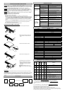
DIRECTIONS TO MOUNT THE UPS IN THE RACK
1. Assemble the handlebars to the rack mount brackets (ears) as
shown in the figures, using the flat head screws (M4.0*8mm)
provided.
2. Assemble the two ears to the both sides of the UPS enclosure as
shown in the figures, using the flat head screws (M5.0*8mm)
provided.
3. Install the UPS at or near the bottom of the rack.
CAUTION! At least two people are required when
mounting the UPS in the rack due to its weight. The battery
pack may be removed while mounting it in the rack.
HARDWARE INSTALLATION GUIDE
1. Your new UPS may be used immediately upon receipt. However,
recharging the battery for at least four hours is recommended to
insure that the battery’s maximum charge capacity is achieved. Charge
loss may occur during shipping and storage. To recharge the battery,
simply leave the unit plugged into an AC outlet.
2. Connect the equipment to your UPS outlets. The IEC-IEC power cords
coming with the unit are used to connect your computer and monitor to
the UPS. Items such as copiers, laser printers, vacuums, space heaters,
or other large electrical devices should not be connected to the UPS.
Please make sure that the total loads of your equipments are less than
the maximum total power load of your UPS.
3. Connect the UPS and a wall outlet by using your PC power cord. Please
avoid using extension cords and adapter plugs. (To maintain optimal battery charge, leave the
UPS plugged in at all times.)
4. Press the UPS power button to turn it on. The “Power On” indicator will be illuminated in “Green”.
5. Install your software and accessories. To use the software, simply connect the enclosed serial
interface cable to the serial port on the UPS and an open serial port on the computer.
BASIC OPERATION
FRONT PANEL AND REAR PANEL DESCRIPTION
◆ Power Switch
Press the power button to turn the UPS ON or OFF.
◆ Test Switch
Press this button to perform a self test of your UPS. This UPS also performs a self test
automatically when powered on. After the UPS passes the test, it returns to on-line
operation. If the UPS fails the self-test, please recharge the battery for at least 4 hours
and perform another self-test. If it fails after recharging the battery, please replace the
battery. In battery mode, you can press this button to silence an audible alarm.
◆ Power On Indicator
This LED is illuminated when the utility condition is normal and the UPS outlets are
providing “clean power”, free of surges and spikes.
◆ AVR Indicator
This LED indicates that the UPS is operating in automatic voltage regulation mode.
When the led is illuminated continuously, it indicates input over-voltage and the UPS
unit bucks the voltage. When the led is flashed in rotation, it indicates that the UPS
unit boosts input voltage.
◆ Using Battery Indicator
This LED illuminates during utility failure, indicating that the battery is supplying
power to the battery-power supplied outlets.
◆ Battery Level Indicator
This indicator shows a visual indication of the battery charge. When battery capacity
is under 20%, no indicator LED will illuminate. If the battery capacity is under 20%
even after 8-hour charge, the batteries may be worn out.
◆
Load Level Indicators
This indicator shows a visual indication of the UPS load. The load indicator LED will turn
orange if the load is between 80% and 100%. If the load is under 20%, no indicator LED
will illuminate.
◆ Circuit Breaker Reset for Overload Protection
Resettable circuit breakers provide optimal overload protection.
◆ Battery Backup and Surge Protection Outlets
The UPS provides 4 battery powered and surge protected outlets for
connected equipment to insure temporary uninterrupted operation
during a power failure and against surges and spikes.
◆ Backup Power for Critical Loads
The UPS provides 2 battery powered, surge protected outlets for the
most critical connected equipment and insures temporary
uninterrupted operation of connected equipment during a power
failure.
NOTE: When the UPS is overloaded, the UPS will interrupt power
supply to the other 4 battery outlets and leave these 2 outlets for
critical loads uninterrupted.
◆Ethernet(RJ-45) Network Protection Ports
These ports are the protection for your computer network cables.
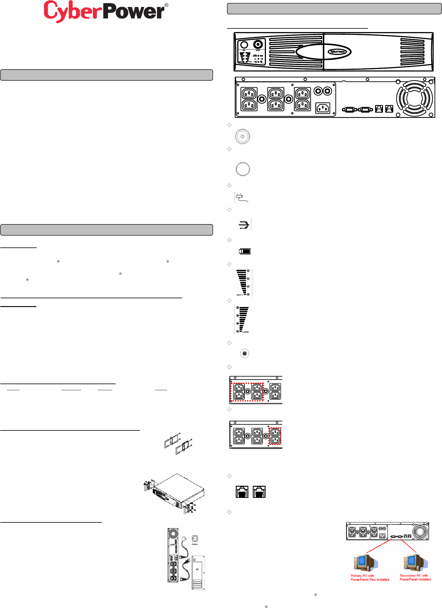
◆ Serial Port to PC
Professional Rack Mount UPS provides two serial
ports to allow connection and communication
between the UPS and two computers.
The two serial ports allow connection and
communication from the DB-9 serial or USB port on
the computer to the UPS unit. These interfaces are
also compatible with the UPS service provided by
Windows 98, Windows ME, Windows 2000,
Windows NT, Windows XP, Windows Server2003
The Primary computer (with PowerPanel Business Edition install ed) is the computer that you will
use to control the UPS and make any change to the operation of the UPS. The Secondary computer
(with PowerPanel installed) is unable to exhibit any control over the UPS.
When there is a power failure, the Primary computer will start to shutdown after a user controlled
delay. Once the Primary computer shuts down, the UPS will signal the secondary computer and
initiate a shutdown. The secondary computer will then shut down. Once the secondary computer has
completed its shutdown, the UPS will power off.
IN OUT
OUT