


PowerConnect B-Series FCX Configuration Guide 447
53-1002266-01
Routing between VLANs
13
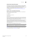
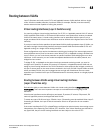
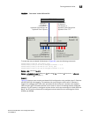
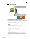
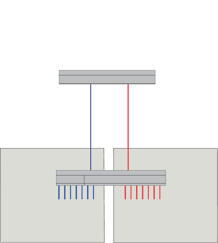
FIGURE 94 Port-based VLANs 222 and 333
To create the two port-based VLANs shown in Figure 94, enter the following commands.
PowerConnect(config)# vlan 222 by port
PowerConnect(config-vlan-222)# untagged ethernet 1 to 8
PowerConnect(config-vlan-222)# vlan 333 by port
PowerConnect(config-vlan-333)# untagged ethernet 9 to 16
Syntax: vlan <vlan-id> by port
Syntax: untagged ethernet [<slotnum>/]<portnum> [to [<slotnum>/]<portnum> | ethernet
[<slotnum>/]<portnum>]
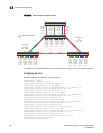
Example 2
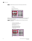
Figure 95 shows a more complex port-based VLAN configuration using multiple Layer 2 Switches
and IEEE 802.1Q VLAN tagging. The backbone link connecting the three Layer 2 Switches is
tagged. One untagged port within each port-based VLAN on device-A connects each separate
network wide Layer 2 broadcast domain to the router for Layer 3 forwarding between broadcast
domains. The STP priority is configured to force device-A to be the root bridge for VLANs RED and
BLUE. The STP priority on device-B is configured so that device-B is the root bridge for VLANs
GREEN and BROWN.
Device
Layer 3 Switch
interface e 1
IP Subnet 1
IPX Network 1
Appletalk Cable-Range 100
Appletalk Zone Prepress
VLAN 222
Ports 1 - 8
VLAN 333
Ports 9 - 16
Port1
Port9
interface e 2
IP Subnet 2
IPX Network 2
Appletalk Cable-Range 200
Appletalk Zone CTP
Ports 1 - 8
IP Subnet 1
IPX Network 1
Appletalk Cable-Range 100
Appletalk Zone Prepress
Ports 9 - 16
IP Subnet 2
IPX Network 2
Appletalk Cable-Range 200
Appletalk Zone CTP