


238 PowerConnect B-Series FCX Configuration Guide
53-1002266-01
Configuring STP related features
8
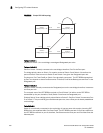
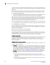
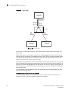
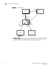
FIGURE 32 Agree stage
At this point, the handshake mechanism is complete between Switch 100, the root bridge, and
Switch 200.
Switch 200 updates the information on the Switch 200 Designated ports (Port2 and Port3) and
identifies the new root bridge. The Designated ports send RST BPDUs, containing proposal flags, to
their downstream bridges, without waiting for the hello timers to expire on them. This process
starts the handshake with the downstream bridges.
For example, Port2/Switch 200 sends an RST BPDU to Port2/Switch 300 that contains a proposal
flag. Port2/Switch 300 asserts a proposed signal. Ports in Switch 300 then set sync signals on the
ports to synchronize and negotiate their roles and states. Then the ports assert a synced signal and
when the Root port in Switch 300 asserts its synced signal, it sends an RST BPDU to Switch 200
with an agreed flag.
This handshake is repeated between Switch 200 and Switch 400 until all Designated and Root
ports are in forwarding states.
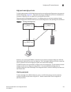
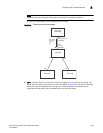
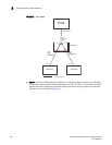
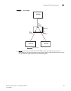
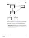
Handshake when a root port has been elected
If a non-root bridge already has a Root port, 802.1W uses a different type of handshake. For
example, in Figure 33, a new root bridge is added to the topology.
BigIron
Switch 100
Root Bridge
Port1
Designated port
Forwarding
Port1
Root port
Synced
Forwarding
RST BPDU
sent with
an Agreed
flag
Switch 200
Switch 300
Switch 400
Indicates a signal
Port2
Synced
Discarding
Port3
Synced
Discarding
Port2
Port3