


PowerConnect B-Series FCX Configuration Guide 247
53-1002266-01
Configuring STP related features
8
Now, Port3/Switch 3 is currently in a discarding state and is negotiating a port role. It received RST
BPDUs from Port3/Switch 2. The 802.1W algorithm determines that the RST BPDUs Port3/Switch
3 received are superior to those it can transmit; however, they are not superior to those that are
currently being received by the current Root port (Port4). Therefore, Port3 retains the role of
Alternate port.
Ports 3/Switch 1 and Port5/Switch 1 are physically connected. Port5/Switch 1 received RST
BPDUs that are superior to those received on Port3/Switch 1; therefore, Port5/Switch 1 is given
the Backup port role while Port3 is given the Designated port role. Port3/Switch 1, does not go
directly into a forwarding state. It waits until the forward delay time expires twice on that port before
it can proceed to the forwarding state.
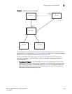
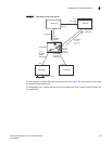
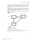
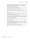
Once convergence is achieved, the active Layer 2 forwarding path converges as shown in Figure 41.
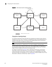
FIGURE 41 Active Layer 2 path
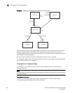
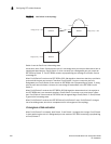
Convergence after a link failure
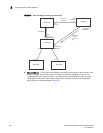
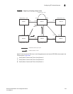
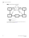
What happens if a link in the 802.1W topology fails?
For example, Port2/Switch, which is the port that connects Switch 2 to the root bridge (Switch 1),
fails. Both Switch 2 and Switch 1 notice the topology change (Figure 42).
Switch 2
Port2
Root port
Port2
Designated
port
Port3
Designated
port
Switch 1
Port5
Backup port
Bridge priority = 1500
Bridge priority = 1000
Port4
Designated port
Port4
Root port
Port3
Designated
port
Port3
Alternate
port
Bridge priority = 2000
Switch 3
Indicates the active Layer 2 path