


444 PowerConnect B-Series FCX Configuration Guide
53-1002266-01
Routing between VLANs
13
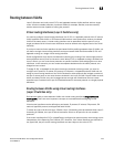
If your backbone consists of virtual routing interfaces all within the same STP domain, it is a
bridged backbone, not a routed one. This means that the set of backbone interfaces that are
blocked by STP will be blocked for routed protocols as well. The routed protocols will be able to
cross these paths only when the STP state of the link is FORWARDING. This problem is easily
avoided by proper network design.
When designing an ISR network, pay attention to your use of virtual routing interfaces and the
spanning-tree domain. If Layer 2 switching of your routed protocols (IP, IPX, AppleTalk) is not
required across the backbone, then the use of virtual routing interfaces can be limited to edge
switch ports within each router. Full backbone routing can be achieved by configuring routing on
each physical interface that connects to the backbone. Routing is independent of STP when
configured on a physical interface.
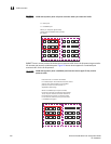
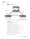
If your ISR design requires that you switch IP, IPX, or Appletalk at Layer 2 while simultaneously
routing the same protocols over a single backbone, then create multiple port-based VLANs and use
VLAN tagging on the backbone links to separate your Layer 2 switched and Layer 3 routed
networks.
There is a separate STP domain for each port-based VLAN. Routing occurs independently across
port-based VLANs or STP domains. You can define each end of each backbone link as a separate
tagged port-based VLAN. Routing will occur independently across the port-based VLANs. Because
each port-based VLAN STP domain is a single point-to-point backbone connection, you are
guaranteed to never have an STP loop. STP will never block the virtual router interfaces within the
tagged port-based VLAN, and you will have a fully routed backbone.
Dynamic port assignment (Layer 2 Switches and
Layer 3 Switches)
All Switch ports are dynamically assigned to any Layer 3 VLAN on Layer 2 Switches and any
non-routable VLAN on Layer 3 Switches. To maintain explicit control of the VLAN, you can explicitly
exclude ports when configuring any Layer 3 VLAN on a Layer 2 Switch or any non-routable Layer 3
VLAN on a Layer 3 Switch.
If you do not want the ports to have dynamic membership, you can add them statically. This
eliminates the need to explicitly exclude the ports that you do not want to participate in a particular
Layer 3 VLAN.
Assigning a different VLAN ID to the default VLAN
When you enable port-based VLANs, all ports in the system are added to the default VLAN. By
default, the default VLAN ID is “VLAN 1”. The default VLAN is not configurable. If you want to use
the VLAN ID “VLAN 1” as a configurable VLAN, you can assign a different VLAN ID to the default
VLAN.
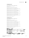
To reassign the default VLAN to a different VLAN ID, enter the following command.
PowerConnect(config)# default-vlan-id 4095
Syntax: [no] default-vlan-d <vlan-id>
You must specify a valid VLAN ID that is not already in use. For example, if you have already defined
VLAN 10, do not try to use “10” as the new VLAN ID for the default VLAN. Valid VLAN IDs are
numbers from 1 – 4095.