


454 PowerConnect B-Series FCX Configuration Guide
53-1002266-01
Configuring IP subnet, IPX network, and protocol-based VLANs within port-based VLANs
13
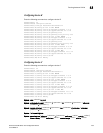
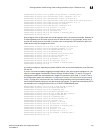
PowerConnect(config-ipx-proto)# atalk-proto name Red
PowerConnect(config-atalk-proto)# no dynamic
PowerConnect(config-atalk-proto)# static ethernet 13 to 25
PowerConnect(config-atalk-proto)# end
PowerConnect# write memory
PowerConnect#
Syntax: ip-subnet <ip-addr> <ip-mask> [name <string>]
Syntax: ipx-network <ipx-network-number> <frame-encapsulation-type> netbios-allow |
netbios-disallow
[name <string>]
Syntax: ip-proto | ipx-proto | atalk-proto | decnet-proto | netbios-proto | other-proto static |
exclude | dynamic ethernet [<slotnum>/]<portnum> [to [<slotnum>/]<portnum>] [name
<string>]
Configuring IP subnet, IPX network, and protocol-based
VLANs within port-based VLANs
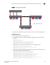
If you plan to use port-based VLANs in conjunction with protocol-based VLANs, you must create the
port-based VLANs first. Once you create a port-based VLAN, then you can assign Layer 3 protocol
VLANs within the boundaries of the port-based VLAN. Generally, you create port-based VLANs to
allow multiple separate STP domains.
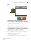
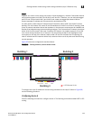
Example
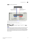
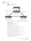
Suppose you need to provide three separate STP domains across an enterprise campus backbone.
The first STP domain (VLAN 2) requires a set of ports at each Layer 2 Switch location to be statically
mapped to IP only. No other protocols can enter the switches on this set of ports.
A second set of ports within STP domain VLAN 2 will be restricted to only IPX traffic. The IP and IPX
protocol VLANs will overlap on Port 1 of device-A to support both protocols on the same router
interface. The IP subnets and IPX network that span the two protocol VLANs will be determined by
the PowerConnect router configuration. The IP and IPX Protocol VLANs ensure that only the ports
included in the each Layer 3 protocol VLAN will see traffic from the PowerConnect router.
The second STP domain (VLAN 3) requires that half the ports in the domain are dedicated to IP
subnet 1.1.1.0/24 and the other ports are dedicated to IPX network 1. Similar to VLAN 2, Port 9
from VLAN 3 will be used to carry this IP subnet and IPX network to the PowerConnect router. No
other protocols will be allowed to enter the network on VLAN 3. Also, no IP packets with a source
address on subnet 1.1.1.0/24 or IPX packets with a source address on network 1 will be allowed to
enter the switches on VLAN 3.
There is no need to segment Layer 3 broadcast domains within the STP broadcast domain (VLAN
4). The PowerConnect router will dictate the IP subnets and IPX network that are on VLAN 4. There
are no Layer 3 protocol restrictions on VLAN 4; however, the PowerConnect router is configured to
only forward IP and IPX between STP domains.