


98 PowerConnect B-Series FCX Configuration Guide
53-1002266-01
Building an IronStack
5
• Static Configuration - A configuration that remains in the database of the Active Controller even
if the unit it refers to is removed from the stack. Static configurations are derived from the
startup configuration file during the boot sequence, are manually entered, or are converted
from dynamic configurations after a write memory command is issued.
• Dynamic Configuration - A unit configuration that is dynamically learned by a new stack unit
from the Active Controller. A dynamic configuration disappears when the unit leaves the stack.
Building an IronStack
This section describes how to build an IronStack. Before you begin, you should be familiar with the
supported stack topologies and the software requirements. When you are ready to build your stack,
you can go directly to the instructions.
IronStack topologies
IronStack technology supports linear and ring stack topologies. Although stackable units may be
connected in a simple linear topology, Dell recommends a ring topology because it offers the best
redundancy and the most resilient operation.
Mixed unit topologies
For more information about PowerConnect B-Series FCX stack topologies, see “PowerConnect
B-Series FCX stack topologies” on page 98.
PowerConnect B-Series FCX stack topologies
A IronStack can contain all one model, or any combination of the PowerConnect B-Series FCX
models. You can mix 24-port and 48-port FCX devices in a single stack, to a maximum of eight units
per stack.
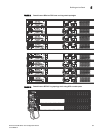
The procedure for cabling a stack of PowerConnect B-Series FCX devices differs depending on
whether your stack contains PowerConnect B-Series FCX-E and PowerConnect B-Series FCX-I
devices. Figure 11 shows PowerConnect B-FCX-S devices cabled in linear and ring stack topologies.
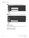
Note that these devices are cabled from the rear panel. Figure 12 shows PowerConnect B-FCX-E
devices in a ring topology stack. Figure 13 shows PowerConnect B-FCX-E devices in a linear
topology stack.
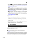
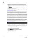
Figure 14 shows a mixed linear topology stack of PowerConnect B-FCX-S, and PowerConnect
B-FCX-E or PowerConnect B-FCX-I devices. Because the PowerConnect B- FCX-E and PowerConnect
B-FCX-I devices are cabled from the front panel, and PowerConnect B-FCX-S and devices are cabled
from the rear panel by default, you need to reconfigure the default stacking ports on PowerConnect
B-FCX-S devices to the ports on the front panel. For more information about reconfiguring default
stacking ports, see “Configuring default ports on FCX devices” on page 111.