


PowerConnect B-Series FCX Configuration Guide 341
53-1002266-01
Metro Ring Protocol (MRP)
10
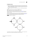
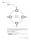
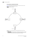
For example, in Figure 61, the ID of all interfaces on all nodes on Ring 1 is 1 and all interfaces on
all nodes on Ring 2 is 2. Port 1/1 on node S1 and Port 2/2 on S2 have the IDs of 1 and 2 since the
interfaces are shared by Rings 1 and 2.
The ring ID is also used to determine an interface priority. Generally, a ring ID is also the ring priority
and the priority of all interfaces on that ring. However, if the interface is shared by two or more
rings, then the highest priority (lowest ID) becomes the priority of the interface. For example, in
Figure 61, all interfaces on Ring 1, except for Port 1/1 on node S1 and Port 2/2 on node S2 have a
priority of 1. Likewise, all interfaces on Ring 2, except for Port 1/1 on node S1 and Port 2/2 on
node S2 have a priority of 2. Port 1/1 on S1 and Port 2/2 on S2 have a priority of 1 since 1 is the
highest priority (lowest ID) of the rings that share the interface.
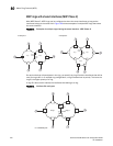
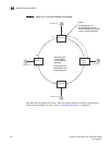
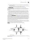
If a node has interfaces that have different IDs, the interfaces that belong to the ring with the
highest priority become regular ports. Those interfaces that do not belong to the ring with the
highest priority become tunnel ports. In Figure 61, nodes S1 and S2 have interfaces that belong to
Rings 1 and 2. Those interfaces with a priority of 1 are regular ports. The interfaces with a priority
of 2 are the tunnel ports since they belong to Ring 2, which has a lower priority than Ring 1.
Selection of master node
Allowing MRP rings to share interfaces limits the nodes that can be designated as the master node.
Any node on an MRP ring that does not have a shared interface can be designated as the ring
master node. However, if all nodes on the ring have shared interfaces, nodes that do not have
tunnel ports can be designated as the master node of that ring. If none of the nodes meet these
criteria, you must change the rings’ priorities by reconfiguring the rings’ ID.
In Figure 61, any of the nodes on Ring 1, even S1 or S2, can be a master node since none of its
interfaces are tunnel ports. However in Ring 2, neither S1 nor S2 can be a master node since these
nodes contain tunnel ports.
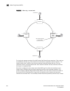
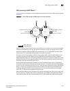
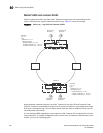
Ring initialization
The ring shown in Figure 58 shows the port states in a fully initialized ring without any broken links.
Figure 62 shows the initial state of the ring, when MRP is first enabled on the ring switches. All ring
interfaces on the master node and member nodes begin in the Preforwarding state (PF).