


786 PowerConnect B-Series FCX Configuration Guide
53-1002266-01
Overview
26
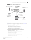
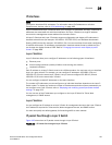
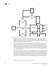
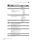
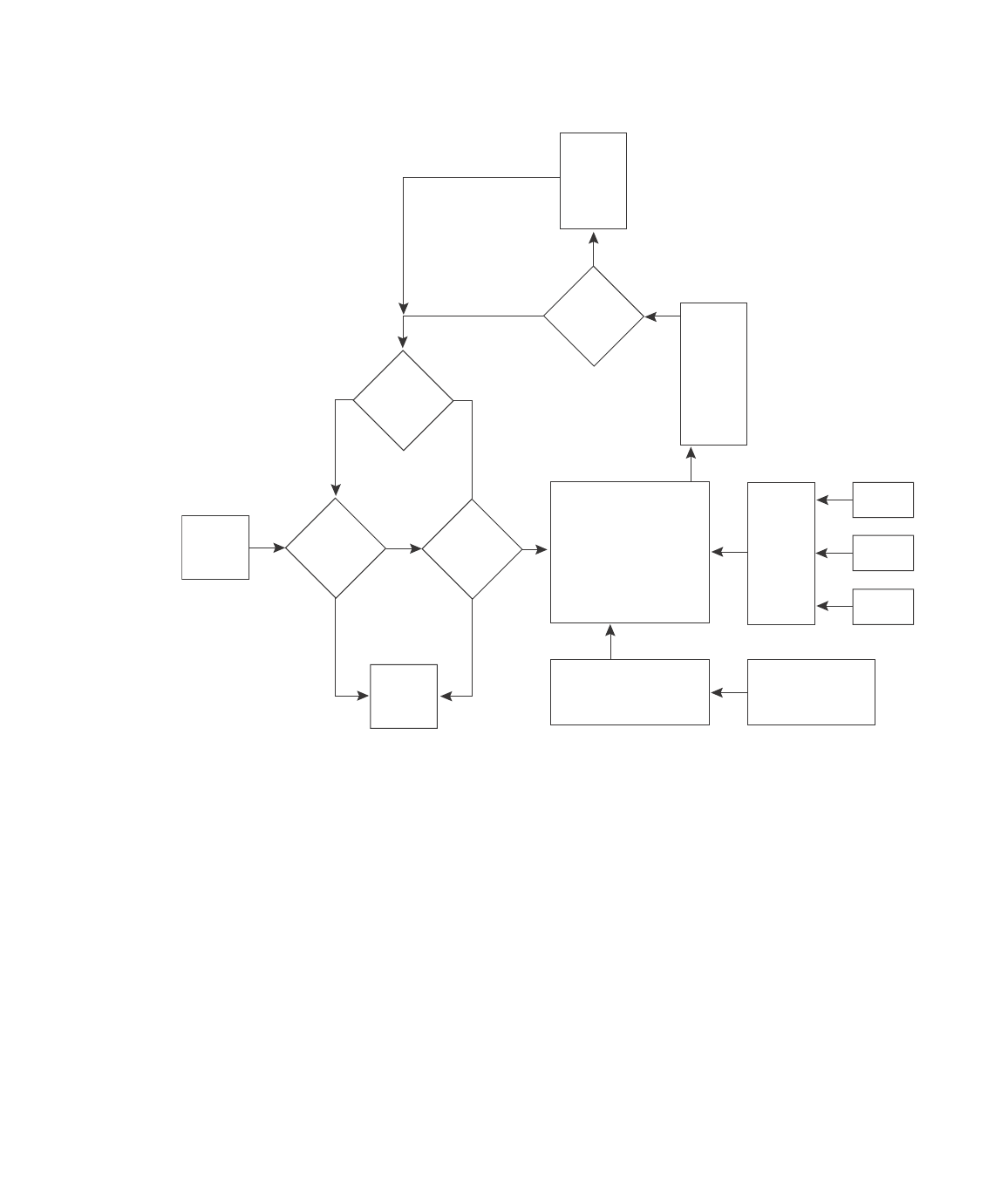
Figure 126 shows the following packet flow:
1. When the Layer 3 Switch receives an IP packet, the Layer 3 Switch checks for filters on the
receiving interface.
1
If a deny filter on the interface denies the packet, the Layer 3 Switch
discards the packet and performs no further processing, except generating a Syslog entry and
SNMP message, if logging is enabled for the filter.
2. If the packet is not denied at the incoming interface, the Layer 3 Switch looks in the session
table for an entry that has the same source IP address and TCP or UDP port as the packet. If
the session table contains a matching entry, the Layer 3 Switch immediately forwards the
packet, by addressing it to the destination IP address and TCP or UDP port listed in the session
table entry and sending the packet to a queue on the outgoing ports listed in the session table.
The Layer 3 Switch selects the queue based on the Quality of Service (QoS) level associated
with the session table entry.
3. If the session table does not contain an entry that matches the packet source address and TCP
or UDP port, the Layer 3 Switch looks in the IP forwarding cache for an entry that matches the
packet destination IP address. If the forwarding cache contains a matching entry, the Layer 3
Switch forwards the packet to the IP address in the entry. The Layer 3 Switch sends the packet
to a queue on the outgoing ports listed in the forwarding cache. The Layer 3 Switch selects the
queue based on the Quality of Service (QoS) level associated with the forwarding cache entry.
Incoming
Port
Outgoing
Port
Session
Table
N
Y
Fwding
Cache
N
Y
N
Y
Y
N
PBR
or
IP acc
policy
IP Route
Table
ARP
Cache
Load
Balancing
Algorithm
Mult.
Equal-
cost
Paths
Lowest
Admin.
Distance
Lowest
Metric
Static ARP
Table
RIP
OSPF
BGP4
1. The filter can be an Access Control List (ACL) or an IP access policy.