


Removing and Replacing Parts 4-39
P
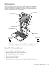
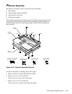
almrest Assembly
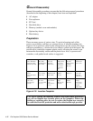
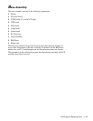
The palmrest assembly consists of the following components:
•
IR assembly
•
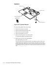
Left and right speaker assemblies
•
Hard-disk drive heat sink
•
Touch-pad assembly
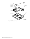
The following subsections provide removal and replacement procedures for the
components of the palmrest assembly. These procedures assume that the key-
board assembly, heat sink, status display panel, and the LCD assembly have
been removed.
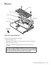
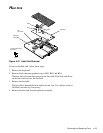
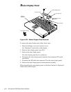
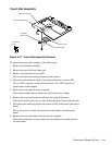
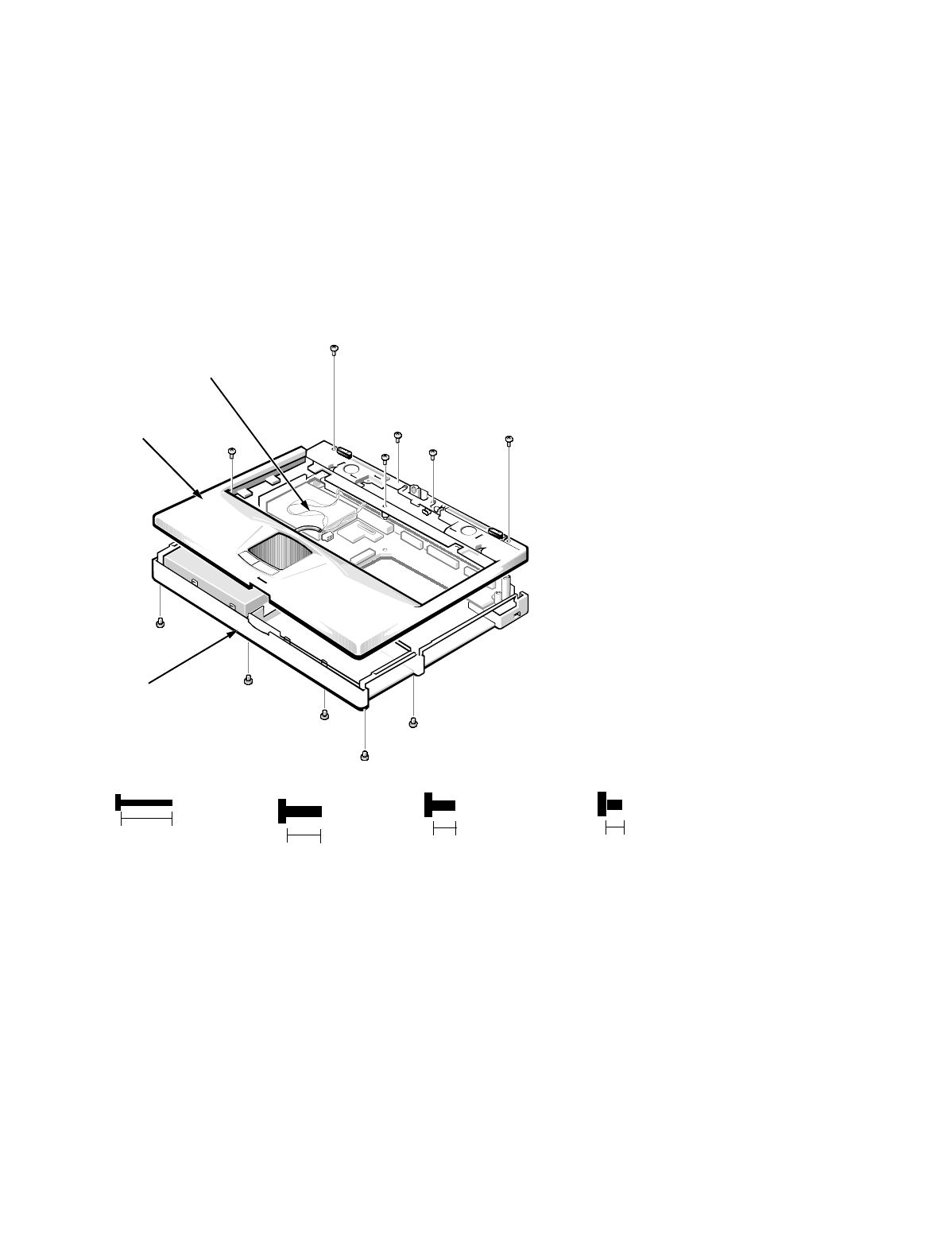
Figure 4-24. Palmrest Assembly Removal
To remove the palmrest assembly, follow these steps:
1. Remove bottom screws B1, B2, B3, B4, and B5.
2. Remove case screws CS1 and CS2.
These screws are to the side of the hinges.
3. Remove case screws CS3 and CS4.
These screws are on either side of the microphone.
palmrest
assembly
base
assembly
(screws CS1 and
CS2 are 8 mm)
wiring
harness
CS1
CS2
CS3
CS4
CS5
CS6
B1
B2
B5
B3
B4
(screws B1, B2, B3, CS5,
and CS6 are 12 mm)
12 mm
(screws CS3, and
CS4 are 5 mm)
8 mm
(screws B4 and
B5 are 3 mm)
3 mm
5 mm