


60 Installing System Components
The following components require address space:
• System ROM
• Advanced Programmable Interrupt Controllers (APIC)
• Integrated PCI devices (such as NICs) and SCSI controllers
• PCI expansion cards
At start-up, the BIOS identifies the components that require address space. The BIOS dynamically
calculates the amount of reserved address space required. The BIOS then subtracts the reserved address
space from 4 GB to determine the amount of usable space.
• If the total installed system memory is less than the usable space, all installed system memory is
available for use only by the operating system.
• If the total installed system memory is equal to or greater than the usable address space, a small
portion of installed memory is available for use by the operating system.
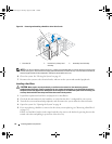
Removing a Memory Module
CAUTION: Many repairs may only be done by a certified service technician. You should only perform
troubleshooting and simple repairs as authorized in your product documentation, or as directed by the online or
telephone service and support team. Damage due to servicing that is not authorized by Dell is not covered by your
warranty. Read and follow the safety instructions that came with the product.
1
Turn off the system and attached peripherals, and disconnect the system from the electrical outlet.
2
Open the system. See "Opening the System" on page 41.
3
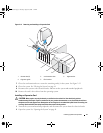
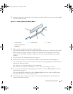
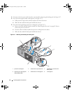
Press out on the securing clip at each end of the memory module connector. See Figure 3-14.
4
Grasp the memory module and pull it out of the connector.
If the module is difficult to remove, gently move the module back and forth to remove it from the
connector.
Installing a Memory Module
CAUTION: Many repairs may only be done by a certified service technician. You should only perform
troubleshooting and simple repairs as authorized in your product documentation, or as directed by the online or
telephone service and support team. Damage due to servicing that is not authorized by Dell is not covered by your
warranty. Read and follow the safety instructions that came with the product.
1
Turn off the system and attached peripherals, and disconnect the system from the electrical outlet.
2
Open the system. See "Opening the System" on page 41.
3
Press on the securing clip at each end of the memory module connector. See Figure 3-14.
4
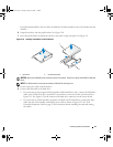
Align the memory module’s edge connector with the alignment key in the connector.
The memory module connector has an alignment key that allows the memory module to be installed
in the connector in only one way.
book.book Page 60 Tuesday, August 25, 2009 1:14 PM