


Installing System Components 71
7
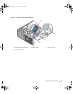
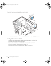
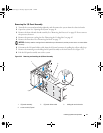
Place the heat sink assembly onto the heat sink assembly bracket and tilt the heat sink assembly down
on the system board. See Figure 3-15.
8
Align the two captive screws with the system board and tighten them to secure the heat sink assembly
to the system board.
9
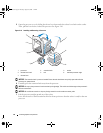
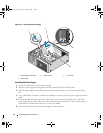
Depending on your system configuration, connect the following power cables:
• P1 and P2 to the system board
• P3 and P5 to the SATA or SAS drives
• P7 to the diskette drive
• P8, P9, and P10 to the optical and tape drives
10
Close the system. See "Closing the System" on page 41.
Chassis Intrusion Switch
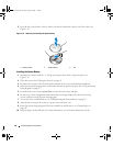
Removing the Chassis Intrusion Switch
CAUTION: Many repairs may only be done by a certified service technician. You should only perform
troubleshooting and simple repairs as authorized in your product documentation, or as directed by the online or
telephone service and support team. Damage due to servicing that is not authorized by Dell is not covered by your
warranty. Read and follow the safety instructions that came with the product.
1
Turn off the system and attached peripherals, and disconnect the system from the electrical outlet.
2
Open the system. See "Opening the System" on page 41.
3
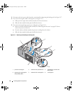
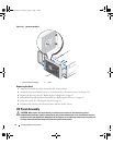
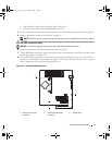
Disconnect the chassis intrusion switch cable from the INTRUDER connector on the system board.
See Figure 3-20.
4
Slide the chassis intrusion switch out of the securing bracket notch. See Figure 3-20.
5
Remove the switch and its attached cable from the system.
book.book Page 71 Tuesday, August 25, 2009 1:14 PM