


78 Installing System Components
9
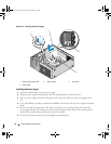
Carefully route any loose cables away from the edges of the system board.
10
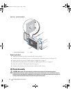
Gently slide the system board toward the front of the system, then lift the system board up and out of
the chassis.
Installing the System Board
1
After removing the old system board, lower the new system board into the chassis, aligning the I/O
ports on the system board with the I/O connector openings on the back panel of the chassis.
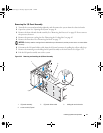
2
Using a #2 Phillips screwdriver, install the eight screws on the system board that secure it to the
chassis. See Figure 3-23.
3
Using a #2 Phillips screwdriver, attach the processor heat sink pivot mount to the system board. See
Figure 3-23.
NOTICE: To prevent damaging the processor, clean the heat sink to remove any thermal grease and then apply
fresh thermal grease to the processor before installing the heat sink.
4
Replace the processor, and the heat sink and shroud assembly. See "Replacing the Processor" on
page 65.
5
Install the memory modules in the same sockets from which they were removed. See "Installing a
Memory Module" on page 60.
6
Install the expansion cards and connect any cables. See "Installing an Expansion Card" on page 57.
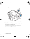
7
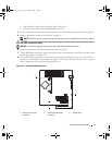
Depending on your configuration, connect the following cables that you removed in "Removing the
System Board" on page 76. See Figure 6-2.
• Two power-supply cables to the POWER and 12VPOWER connectors
• If applicable, diskette data cable to the FLOPPY connector
• I/O panel cable to the FRONTPANEL connector
• 5.25-inch device data cable to the IDE connector
• Processor cooling fan cable to the FAN_CPU connector
• Card cage cooling fan cable to the FAN_CARD_CAGE connector
• SATA hard-drive data cable(s) to the SATA connector(s)
• Intrusion switch cable from the INTRUDER connector
8
Close the system. See "Closing the System" on page 41.
9
Reconnect the system to the electrical outlet, and turn on the system.
book.book Page 78 Tuesday, August 25, 2009 1:14 PM