


Warning
ADP485-01 is an OPEN-TYPE. Please place the module in an enclosure away from airborne dust or high
humidity and prevent electric shock or sudden shock on ADP485-01. Also, it is equipped with protective
method such as some special tool or key to open the enclosure, so as to avoid the hazard to users or any
damage to the module. Do NOT touch terminals when power on.
When many devices are connecting in serial, their Baud rate and communication format setting should be
the same. Also, each device must have individual Unit Address.
I/O terminal screw should be tightened between 1.95kg-cm (1.7 in-lbs). Use copper conductor only,
60/75°C.
Introduction
ADP485-01 is mainly designed to connect Delta product by RS-485 interface. It is equipped with surge
absorber and limited current protection to ensure safe connection of different devices. Also, 120Ω
terminating resistance selection is available. This module enables Delta products to connect one
another by RS-485 interface with much concern of safety and wide application.
ADP485-01 offers four different connectors to enable the network connection for Delta’s PLC DVP
series, HMI DOP series, AC Motor Drive VFD series and Servo drive ASD series.
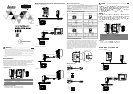
Product Profile
32
6
60
3
106,8
90
6
8
7
3,4
1
2
3
4
5
Unit: mm
1
Mounting plate
5
ON/OFF of terminating resistor (default setting: OFF)
2
COM1 (DB9 female)
6
DIN rail (35mm)
3
COM2 (DB9 male)
7
RS-485 port
4
Nameplate
8
RJ12
Optional Connecting Cable
ADPCAB03A: ADP485-01 ASD-A connecting cable/30cm
ADPCAB03B: ADP485-01 ASD-B connecting cable/30cm
ENGLISH
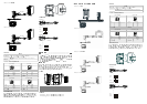
RS-485 Network Connection with Delta Products
ADP485-01 VFD (AC Motor Drive)
RS-485 network
RJ12
ADP485-01 DOP (HMI)
RS-485 network
F1
F3
F2
HMI DOP Series
COM1 COM2
one by one wiring
DB9 male connector
DB9 male connector
connect to COM 1
ADP485-01 ASD-A (Servo Drive)
RS-485 network
Connecting cable (ADPCAB03A)
ADP485-01 ASD-B (Servo Drive)
RS-485 network
Connecting cable (ADPCAB03B)
Environmental Specification
Environment
Operation 0°C ~ 55°C (temperature), 50 ~ 95% (humidity), pollutant degree 2
Storage -25°C ~ 70°C (temperature), 5 ~ 95% (humidity)
Vibration/Shock
resistance
International Standard: IEC 61131-2, IEC 68-2-6 (TEST Fc)/IEC 61131-2 & IEC
68-2-27 (TEST Ea)
COM1, COM2, and RJ12 PIN Explanation
COM1-DB9 female
RJ12-VFD
1
2
3
4
5
6
7
8
9
PIN Definition PIN Definition
1 RS485- 1 +15V
2 RS485+ 2 GND
3 RS485+ 3 SG-
4 RS485- 4 SG+
5, 6, 7, 8, 9: NC
5, 6: Reserved
COM2-DB9 male
RJ12-ADP485-01
5
2
1
4
3
6
7
8
9
PIN Definition PIN Definition
3, 6 RS485- 3 RS-485+
8 RS485+ 4 RS-485-
5, 9 GND 5 GND
1, 2, 4, 7: NC
1, 2, 6: NC
Use of Terminating Resistance
In all RS-485 installations, the cable must be correctly terminated with two sets of resistors,
one set at
each end of the network (4,000 feet maximum total cable length). This applies even if you are only
using one slave node connected to one master device. The terminating resistors prevent reflection
problems that can interfere with data transmission. The resistance value of the terminating resistors
should match the characteristic impedance of the cable. A typical value is 120 ohms. The terminating
resistors must be placed at the two farthest ends of the RS-485 network, regardless of where the
master device is. In some cases master device RS-485 ports have built in or optional terminating
resistors. Beware of your network (whether it has one node or 32 nodes) having only two sets of
terminating resistors.
Termination Resistor Switch
Cable Connection
ADPCAB03A
DB9 male
1394 male
1
2
3
4
5
6
7
8
9
1
5
6
3
2
4
RS485 -
RS485 +
GND
ADPCAB03B
DB9 male
Mini DIN
1
2
3
4
5
6
7
8
9
8
1
3
6
RS485 -
RS485 +
GND
(Open Type)
( : )
(Baud rate) (Format)
(Unit address)
/ 1.95kg-cm (1.7 in-lbs) 60°C/75°C
RS-485
ADP485-01 (120Ω)
RS-485
ADP485-01 PLC DVP DOP
VFD ASD RS485
32
6
60
3
106,8
90
6
8
7
3,4
1
2
3
4
5
mm
1
5
OFF
2
COM1 (DB9 )
6
DIN (35mm)
3
COM2 (DB9 )
7
RS-485
4
8
RJ12
ADPCAB03A ADP485-01 ASD-A /30
ADPCAB03B ADP485-01 ASD-B /30
RS-485
ADP485-01 VFD
RS-485
RJ12
VFD Series
ADP485-01 DOP
RS-485
F1
F3
F2
DOP
COM1 COM2
1 1
DB9DB9
COM 1