


ASD-PU-01B
Digital Keypad / Display
Instruction Sheet
1 General Notes
This instruction sheet will be helpful in the installation and operation of Delta ASD-PU-01B. Before
using the product, please read this instruction sheet to ensure correct use. You should thoroughly
understand all safety precautions before proceeding with the installation and operation, and place
this instruction sheet in a safe location for future reference.
If you do not understand please contact your local Delta sales representative.
Please observe the following precautions:
z
Do not use the product in a potentially explosive environment.
z
Install the product in a clean and dry location free from corrosive and inflammable gases or
liquids.
z
Please ensure all wirings are correct. Otherwise, damage, malfunction or inability may
result.
z
Do not shake, strike, hammer or throw the product. Failure to observe this precaution or
perform improper operation may seriously damage the product or cause personal injury.
z
Do not damage the cables or/and disassemble the product as doing this will cause electric
shock and result in serious injury or damage to the product.
2 Safety Precautions
ASD-PU-01B is the specified digital keypad / display used with Delta ASDA-B series servo drives.
It is provided with 4 groups built-in memories for saving and writing drive parameters. Also, there
are several special function keys: MODE, SHIFT, SET and FUNC (including fast editing, reset,
parameter read & write, JOG, servo motor dynamic & static auto-tuning functions) on the keypad
and can offer more flexible and convenient operation.
When connecting ASD-PU-01B and ASDBCADK0001 communication cable, if the screws are
necessary, φ3*1.06*8 screws are recommended for use.
Ensure to observe the following precautions when performing unpacking check, installation, wiring
and operation.
Unpacking Check and Installation
¾ Please ensure that both the digital keypad and servo drive are correctly matched. Failure to
observe this precaution may cause damage, malfunction or inability.
¾
Do not install the product in a location that is outside the stated specification for the digital
keypad and servo drive. Failure to observe this caution may cause fire, seriously damage the
digital keypad and servo drive or cause personal injury.
Wiring
¾ Please pay close attention on the connectors and wire terminations. Ensure all wirings are correct
and secure. Otherwise, damage, malfunction or inability may result.
Operation
¾ Do not shake, strike, hammer or throw the product. Failure to observe this precaution or perform
improper operation may seriously damage the product or cause personal injury
.
Maintenance and Inspection
¾ Do not damage the cables. Never disassemble the product. Doing this will cause electric shock and
result in serious injury or damage to the product.
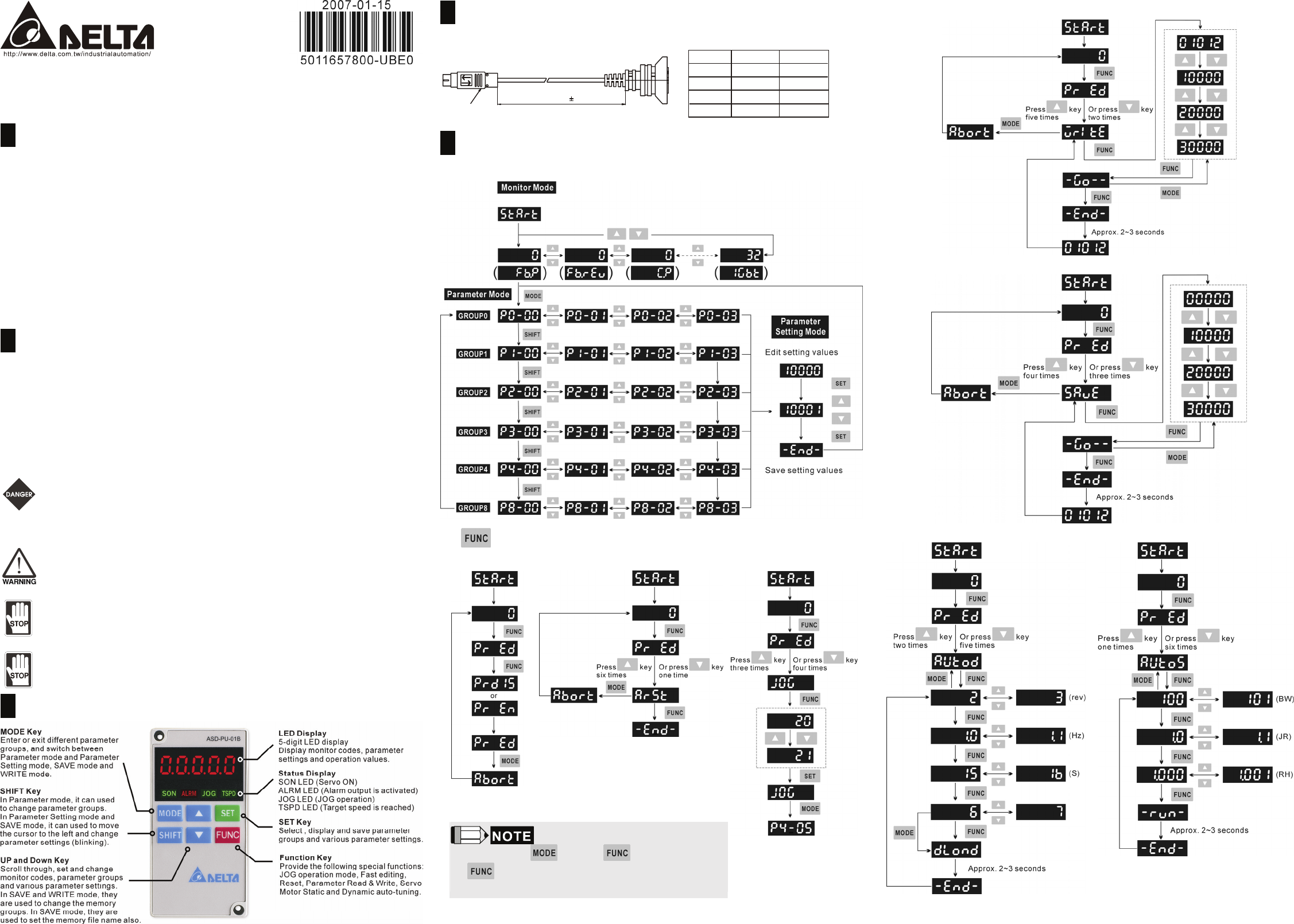
3 ASD-PU-01B Features
4 Communication Cable (Connecting a Keypad to a ASDA-B)
Delta Part Number: ASDBCADK0001
1000mm 15
Mini-Din 8-Pin
Title
Part No. Manufacturer
BoxHeader
Cover
Housing
Terminal
2541-T-G
2541-K-14PD
3140311100
3071420300 DELTA
JAWS
DELTA
JAWS
5 ASD-PU-01B Display Flowchart
Monitor Mode, Parameter Mode and Parameter Setting Mode
Display Flowchart
Fast Editing Reset JOG
¾ If the user press key to exit mode, when entering
mode next time, the code of the last operation mode that the
user used last time will show on the LED display.
Parameter Write Mode (Parameter settings written out to the Drive)
Parameter Save Mode (Save parameter settings to the Keypad)
Servo Motor Dynamic Auto-tuning Servo Motor Static Auto-tuning