


2007-10-12
5011644001-LWT1
LonWorks Communication Module (CME-LW01) Instruction Sheet
Lonworks is a registered trademark of Echelon Corporation.
Please thoroughly read and understand the following contents to ensure correct use before operation.
The content of this instruction sheet may be revised without prior notice. Please consult our distributors or
download the most updated version at http://www.delta.com.tw/industrialautomation
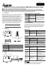
A. Introduction
Device CME-LW01 is used for communication interface between
Modbus and LonTalk. CME-LW01 needs be configured via
LonWorks network tool first, so that it can perform the function on
LonWorks network. No need to set CME-LW01 address.
This manual provides instructions for the installation and setup for
CME-LW01 that is used to communicate with Delta VFD-E
(firmware version of VFD-E should conform with CME-LW01
according to the table below) via LonWorks Network. The content
of this instruction sheet may be revised without prior notice.
Please consult our distributors or download the most updated
version at http://www.delta.com.tw/industrialautomation.
Delta AC Drive
Series Firmware Version
VFD-E Version 2.02 or higher
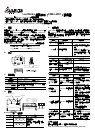
B. Dimensions
5
7
.
3
[
2
.
2
6
]
72.2 [2.84]
5
9
.
7
[
2
.
3
5
]
9
.
5
[
0
.
3
7
]
3.5 [0.14]34.8 [1.37]
SP
CME-LW01
C. Specification
Power supply 16-30VDC, 750mW
Communication Modbus in ASCII format, protocol: 9600, 7, N, 2
LonTalk free topology with FTT-10A 78 Kbps
LonTalk terminal
4-pin terminal, wire gauge: 28-12 AWG, wire strip
length: 7-8mm
RS-485 port 8 pins with RJ-45
D. Wiring
SP
CME-LW01
Power LED
SP LED
Service LED
Service Pin
1: Reserved
2: EV
3: GND
4: SG-
5: SG+
6: Reserved
7: Reserved
8: Reserved
LonTalk
1
234
LonTalk
Terminal definition for LonTalk system
Terminal Symbol Function
1
2
3
4
These are twisted pair cables
to connect to LonTalk system.
Terminals 1 and 2 should be
used as one group, and the
same for terminals 3 and 4.
E. LEDs Indications
There are three LEDs in front panel of CME-LW01. If the
communication is normal, power LED, SP LED should be green
(red LED means abnormal communication) and service LED
should be OFF. If LEDs display do not match, refer to user
manual for details.
Power LED
State Description Corrective Actions
Green LED
Power is on and
CME-LW01 works
LED is OFF
Power on or program is
abnormal
1. Check if power is 24V or
plug is loose.
2. Check if flash memory IC is
well-inserted to the socket.
SP LED
State Description Corrective Actions
Green LED
It communicates to AC
drive
Blinked Green
LED
CME-LW01 reads default
setting from AC drive
Red LED Disconnect or time-out
1. Check if cable is loose.
2. Check if the communication
protocol is properly set.
Service LED
State Description Corrective Actions
LED blinks at
1/2 Hz rate
This is the normal
situation for an
un-configured device
LED is OFF Bad hardware device
Check if anything wrong with
power supply, clock or
Neuron chip.
LED is ON
continuously,
even when
power is first
applied to the
device.
Bad hardware device
1. Check if anything wrong
with power supply, clock or
Neuron chip.
2. Check if there is a short
circuit between pin 17 and
18.
LED blinks at
power-up,
goes OFF,
then ON
solid.
This is the normal
situation for an
application-less device.
If the device is not an
application-less, then it could
be memory problems or
application code errors. A
self-test failure can also turn
the LED ON solid.
NOTE
Please download the XIF file and user manual at
http://www.delta.com.tw/industrialautomation/