


DeviceNet Communication Module Instruction Sheet
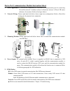
1. Panel Appearance: 1) For RS-485 connection to VFD series 2) Communication port for connecting
DeviceNet network 3) Address selector 4) Baud rate selector 5) Three LED status
indicators for monitor. (Refer to the figure below)
2. Network Wiring: Picture right hand side below shows rough wire configuration. Refer to DeviceNet
wiring spec for physical wire connection.
3. Mounting Method: Picture right hand side below shows how to mount this communication module
onto DIN Rail
SP
Module
Network
Data Rate
ADD1
ADD2
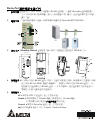
42.0 [1.65]
100.0 [3.94]
34.0 [1.34]
92.0 [3.62]
4. Power Supply: No external power needed. Power is supplied via RS-485 that is connected to VFD
series. Six pins RJ-11, which is packed together with this communication module, is
used to connect the RS-485 between VFD series and this communication module for
power. This communication module will perform the function once is connected. Refer
to following paragraph for LED indications.
5. LEDs Display:
SP: Green LED means in normal communication, Red LED means abnormal.
Module: Green blink LED means no I/O data transmission, Green steady LED means I/O data
transmission OK.
Red LED blinking or Red LED mean module communication is abnormal.
Network: Green LED means DeviceNet in normal communication, Red LED means abnormal
★ Refer to user manual for detail information-- Chapter 5 Troubleshooting.