


http://www.delta.com.tw/industrialautomation/
Temperature Controller
Instruction Sheet
Thank you very much for purchasing DELTA DTC1000/2000 Series Temperature Controller. Please read this
instruction sheet before using your DTC1000/2000 series to ensure proper operation, and please keep this instruction
sheet handy for quick reference.
Caution
DANGER! Caution! Electric Shock!
DTC1000/2000 series is an OPEN-TYPE device and therefore should be installed in an enclosure free of airborne
dust, humidity, electric shock and vibration. The enclosure should prevent non-maintenance staff from operating the
device (e.g. key or specific tools are required to open the enclosure) in case danger and damage on the device may
occur.
WARNING!
1. Prevent dust or metallic debris from falling into the controller that will cause malfunction. DO NOT modify or
disassemble the controller. DO NO use extra terminals.
2. Do not install and/or use the controller in places subject to:
dust or corrosive gases and liquid high humidity and high radiation vibration and shock
3. Switch off the power when wiring or changing input sensors.
4. Be sure to use compensating wires that match the thermocouple types when extending or connecting the
thermocouple wires.
5. Shorten the wire when wiring a platinum resistance thermometer (RTD) to the controller, and separate power cable
from load wires to prevent interference and conductive influence.
6. Make sure the power cable and signals device are installed correctly before switching on the power of
DTC1000/2000; otherwise serious damage may occur.
7. DO NOT touch the terminals or repair the controller when the power is on to prevent electric shock.
8. Wait at least one minute after the power is off to allow the capacitor to discharge. DO NOT touch any inter
nal circuit
within this period.
9. DO NOT touch the internal terminals no matter the power is on or off.
10. DO NOT place other heating source (e.g. power supply) in parallel with DTC1000/2000 during the installation.
Please keep proper space in between.
Model Name Explanation
DTC
1234
5
Series name DTC: Delta C series temperature controller
1 Controller position
1: First controller
2: Controller connected in parallel
2 Auxiliary output
groups
0: standard, 2 outputs, no auxiliary output
1: 1 auxiliary output. Not available now.
2: 2 auxiliary outputs. Not available now.
3 4 Optional
00: Standard
01: CT input. Not available now.
02: EVENT input. Not available now.
5 Main output type
R: Relay output SPST, 250VAC, 3A
V: Voltage pulse output 12V +10% ~ -20%
C: Current output 4 ~ 20mA
L: Linear voltage output 0 ~ 10V
Enclosed functions: DC24V input, 2 outputs, relay output for output 2, RS-485 communication.
Function & Specification
Power supply DC24V. Isolated switching power
Voltage range Rated voltage: 90% ~ 110%
Power consumption Rated 24 VDC, Max. 24 W combined, 3W + 3W x number of DTC2000 controllers (Max. 7)
Thermocouple: K, J, T, E, N, R, S, B, L, U, TXK
Platinum RTD: Pt100, JPt100
Input sensors
Linear DC input: 0 ~ 5V, 0 ~ 10V, 0 ~ 20mA, 4 ~ 20mA, 0 ~ 50mV
Sampling rate Analog input: 0.15 sec. Thermocouple or platinum RTD: 0.4 sec.
Control method PID , programmable PID, Manual, ON/OFF
Relay: SPST, Max. load 250VAC, 3A resistive load
Voltage pulse: 12VDC, Max. output current: 40mA
Current: DC 4 ~ 20mA (Load resistance: < 500Ω)
Output types
Analog voltage: 0 ~ 10V (Load resistance: > 1,000Ω)
Output function
Control output, alarm output, proportional output
Proportional output is available only when output 1 is linear voltage/current output.
Alarm 12 alarm modes
Communication RS-485 digital communication, 2,400bps ~ 38,400bps
Communication protocol
Modbus protocol, ASCII/RTU format
Internal connection Internal terminals available to transmit 24V power supply and communication signals
Vibration resistance 10 ~ 55Hz, 10m/s
2
for 10mins, each in X, Y and Z direction
Shock resistance Max. 300m/s
2
, 3 times in each 3 axes, 6 directions
Ambient temperature 0 ~ 50
°
C
Storage temperature -20 ~
+65
°
C
Altitude < 2,000m
Ambient humidity 35% ~ 85% RH (non-condensing)
Pollution degree 2
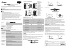
Product Profile & Outline
DTC1000R/V/C/L
1 RUN/STOP switch
2 Wiring and Model name
3 DIN rail clip
4 I/O terminals
5 LED indicators
6 Mounting hole
7 Specification label
8 Extension port
9 Extension clip
10
DIN rail
11
RS-485 communication port
12
Extension clip
13
DC power input
9
0
.
0
3
.
0
60.03.4
25.2
4
.
0
3
.
0
1
2
3
4
5
6
7
8
9
10
3
11
12
13
DTC2000R/V/C/L
1 Wiring and Model name
2 DIN rail clip
3 I/O terminals
4 LED indicators
5 Mounting hole
6 Specification label
7 Extension port
8 Extension clip
9 DIN rail
9
0
.
0
3
.
0
60.03.4
25.2
4
.
0
3
.
0
1
2
3
4
5
6
7
8
9
2
10
10
Extension port
Input
DTC1000/2000 series supports the following input sensors:
Input Sensor Register Value Available Range
0 ~ 50mV linear voltage input 17 0 ~ 50mV
4 ~ 20mA linear current input 16 4 ~ 20mA
0 ~ 20mA linear current input 15 0 ~ 20mA
0 ~ 10V linear voltage input 14 0 ~ 10V
0 ~ 5V linear voltage input 13 0 ~ 5V
Platinum RTD (Pt100) 12 -200 ~ 600
°
C (-328 ~ 1,112
°
F)
Platinum RTD (JPt100) 11 -20 ~ 400
°
C (-4 ~ 752
°
F)
Thermocouple TXK type 10 -200 ~ 800
°
C (-328 ~ 1,472
°
F)
Thermocouple U type 9 -200 ~ 500
°
C (-328 ~ 932
°
F)
Thermocouple L type 8 -200 ~ 850
o
C (-328 ~ 1562
°
F)
Thermocouple B type 7 100 ~ 1,800
°
C (212 ~ 3,272
°
F)
Thermocouple S type 6 0 ~ 1,700
°
C (32 ~ 3,092
°
F)
Thermocouple R type 5 0 ~ 1,700
°
C (32 ~ 3,092
°
F)
Thermocouple N type 4 -200 ~ 1,300
°
C (-328 ~ 2,372
°
F)
Thermocouple E type 3 0 ~ 600
°
C (32 ~1,112
°
F)
Thermocouple T type 2 -200 ~ 400
°
C (-328 ~ 752
°
F)
Thermocouple J type 1 -100 ~ 1,200
°
C (-148 ~ 2,192
°
F)
Thermocouple K type 0 -200 ~ 1,300
°
C (-328 ~ 2,372
°
F)
Note 1: The current input is built-in with 249Ω precision resistor. See “How To Set up Current Input” section.
Note 2: Default setting: Pt100 input.
The range of linear input and feedback value is adjustable. Range of input feedback: -999 ~ 9,999. Take 0 ~ 20mA input
as example, -999 refers to 0mA input, and 9,999 refers to 20mA input. If we change the range to 0 ~ 2,000, 0 will refer to
0mA input, and 2,000 will refer to 20mA input. 1 display scale = 0.01mA.
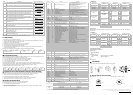
Output
There are several output types available from DTC1000/2000 series: Control Output (heating/cooling), Alarm Output
and Proportional Output.
y Control Output
DTC1000/2000 series offers 2 outputs for heating or cooling control. If you require dual loop output, the 2 outputs
should be set to different actions (heating or cooling). If you require the 2 outputs are set to the same control action, only
the control cycle of output 1 will be valid, and the 2 outputs will act at the same time.
The control methods include: PID control, ON/OFF control, Manual control and programmable PID control.
y Single Output Control
Heating hysteresis
ON
OFF
PV
Figure1: ON/OFF Control
Cooling hysteresis
Heating
Cooling
Set Point
Set Point
PV
100%
0
Heating
Output
PV
100%
0
Output
Set Point
Cooling
Set Point
Figure 2: PID Control, Cooling) Control
Figure 3: PID Control, Heating Control
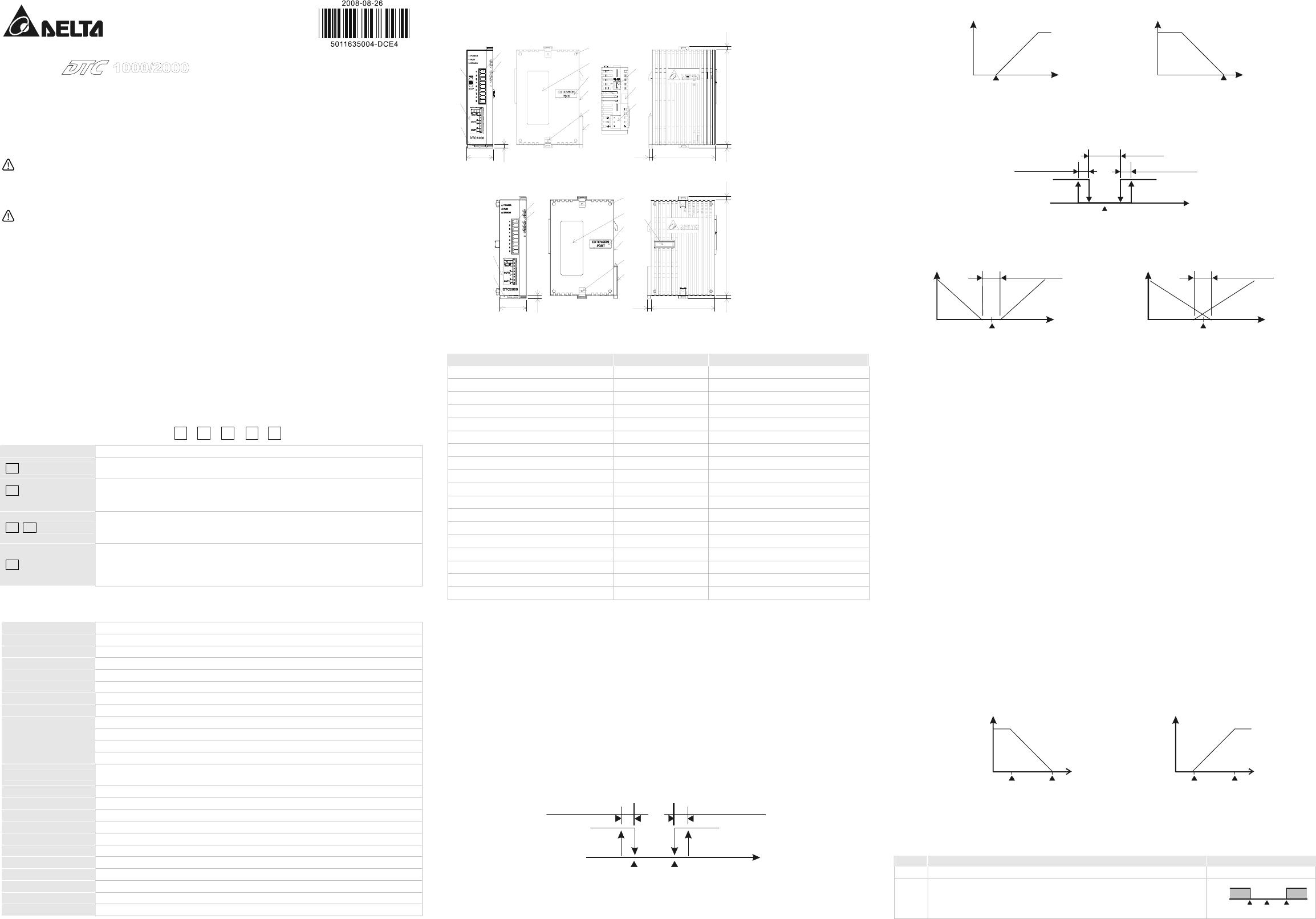
y Dual Output Control
OFF
PV
Set Point
ON
Heating
Deadband
Heating hysteresis
Figure 4: ON/OFF Control
Cooling hysteresis
Cooling
Deadband: Dead
Bandwidth: Negative
PV
0
PV
0
Deadband: Dead
Bandwidth: Positive
Output
Heating Cooling
Set Point
Output
Heating
Cooling
Set Point
Figure 5: PID control
Figure 6: PID Control
y Programmable PID Control & Parameters Setting
The programmable PID control includes 8 patterns (Pattern 0 ~ 7). Each pattern contains 8 steps (Step 0 ~ 7) and
parameters: “link pattern”, “cycle” and “the number of steps”.
Start Pattern: The user can set up which pattern is the start pattern for the programmable control.
Steps: Includes the settings of the two parameters, set point X and execution time T, indicating that the set point (SV)
has to rise to temperature X after the period of execution time T. If the result of the set point X is the same as that of
the previous setting, the process is called “Soak”; otherwise, it is called “Ramp”. Therefore, the programmable control
is also known as Ramp/Soak control. The default setting of the first step is Soak control. The temperature will first rise
to the set point X and remain at X. The total execution time is T.
Link Pattern: The pattern to be executed following the current pattern. If the setting is not 0 ~ 7, the set point will
remain at the last pattern.
Cycle: The additional number of cycles for a pattern. For example, if the parameter is set to 2, it refers to the pattern
has to execute additional twice, totaling the execution to 3 times including the original one.
The Number of Steps: The number of steps in each pattern (range: 0 ~ 7). For example, if the parameter is set to 2,
it refers to the pattern will execute Step 0 ~ Step 2, and other steps will not be executed.
The Execution: Available settings include “run”, “program hold”, “program stop” or “stop”.
1. When this parameter is set to “run”, the program will start its execution from step 0 of the start pattern.
2. When this parameter is set to “program hold”, the program will stop and the temperature will stop at the SV before
the program stops. If the user sets to “run” again, the program will resume the step before the program stops and
execute by the remaining time.
3. When this parameter is set to “program stop”, the program will stop and the temperature will stop at the SV before
the program stops. If the user sets to “run” again, the program will execute again from Step 0 of the start pattern.
4. When this parameter is set to “stop”, the program will stop, and the control output will be disabled.
Proportional Output:
If Output 1 of this DTC1000/2000 series is linear voltage or current, the user can set it to “Proportional Output”.
Proportional output refers to the output varies with the input. For example, if the input range is set to 0 ~ 1,000, and
when the input value is 0, the output will be 0mA or 0V. When the input value is 1,000, the output will be 20mA or 10V.
Figure 7: Proportional Output
Output
PV Low
PV High
Output
10V or 20mA
0V or 4mA
PV Low
PV High
Negative
output slope
PV
PV
Positive output slope
10V or 20mA
0V or 4mA
y Alarm Output
DTC1000/2000 series offers 12 alarm modes. When the PV exceeds or falls below SV, the alarm output will be enabled.
See the table below for the 12 modes.
Mode
Alarm Type Alarm Output Operation
0 No alarm OFF
1
Alarm output will be enabled when the temperature reaches upper and lower
limits.
y Alarm will be enabled when the PV exceeds SV + AL-H or falls below SV –
AL-L.
ON
OFF
AL-L SV AL-H