


DTE Accessory
Instruction Sheet
Thank you very much for choosing DTE-2DS. Please read this instruction sheet before using your DTE-2DS to ensure
proper operation. Keep this instruction sheet handy for quick reference.
Warning
1. Please hold the plastic terminal when installing DTE-2DS to prevent electrostatic discharge (ESD).
2. Prevent dust or metallic debris from falling into the device and cause malfunction. DO NOT
modify
or uninstall DTE-2DS without being permitted. DO NOT
use empty terminals.
3. When installing DTE-2DS, please make sure the power of DTE main unit is switched off and insert
DTE-2DS into the correct slot on DTE main unit.
4. Make sure you install DTE-2DS correctly before switching on the power; otherwise serious damage
may occur.
5. DO NOT
touch the terminals or repair the device when the power is on; otherwise an electric shock
may occur.
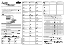
Product Outline & Dimension
Electrical Specifications
Input power DC +5V
Power consumption
Max. 0.5W
Display
Single row 7-segment LED display, two 4 bits
PV: red SV: green
Keys 4 keys for selecting, changing pages and tuning
Terminal connection
Can only be inserted into the “Display and Setup Unit” slot on DTE main unit
Setting up Parameters
Switching modes: DTE-2DS is in ”operation mode” when the power is switched on, Press to enter
“regulation mode”. Press for more than 3 seconds in the operation mode to enter “initial setting
mode”. Press
in the regulation mode or initial setting mode to return to the operation mode.
PV/SV: Displaying the present value and set value. Use
to change the set value.
How to set up: Use
in the three modes to select the parameter to be set up and to
modify the settings. Press
to save the setting.
How to switch modes by keys and set up parameters:
Regulation Mode Operation Mode Initial Setting Mode
Select channel
Press
V
Use
to set up target
temperature (SV)
Press
V
Set up input type
Press
V
Auto-tuning
(Set it up when in PID control and
RUN)
Press
V
Control loop RUN/STOP
Press
V
Set up temperature unit
Press
V
Regulation Mode Operation Mode Initial Setting Mode
PID proportional band
(Set it up when in PID control)
Press
V
Set up start pattern
(Set it up when in PID control)
Press
V
Set up upper limit of
temperature
Press
V
Set up PID Ti value
(Set it up when in PID control)
Press
V
Set up start step
(Set it up when in PID program
control)
Press
V
Set up lower limit of
temperature
Press
V
Set up PID Td value
(Set it up when in PID control)
Press
V
Set up the position of
decimal point
(Not
for thermocouple R, S, B type)
Press
V
Select control mode
Press
V
or
Set up PD/PID control offset
(When in PID control, set up PdoF
when Ti=0. AT sets up ioF
automatically when Ti≠0.)
Press
V
or
Without/with group INB
Set up upper limit of Alarm 1
Press
V
Set up output 1
(Heating, cooling or proportional
output)
Press
V
Hysteresis for output 1
(Set it up when in ON/OFF control)
Press
V
or
Without/with group INB
Set up lower limit of Alarm 1
Press
V
Set up output 2
(Heating, cooling or alarm output)
Press
V
Hysteresis for output 2
(Set it up when in ON/OFF control)
Press
V
Without group INB
Set up upper limit of Alarm 2
Press
V
or
Without/with group INB
Set up Alarm 1 mode
Press
V
Control cycle for output 1
(Set it up when in PID/programmable
PID/manual control)
Press
V
Without group INB
Set up lower limit of Alarm 2
Press
V
Without group INB
Set up Alarm 2 mode
Press
V
Control cycle for output 2
(Set it up when in PID/programmable
PID/manual control)
Press
V
For locking the keys on the
panel
Press
V
Set up copy function
Press
V
Ratio of output 1 & output 2
when in dual output control.
Pb2 = Pb1 × COEF
(Set it up when in PID/programmable
PID + dual output)
Press
V
For displaying and tuning
the value of output 1
(Displayed when in
PID/programmable PID/manual
control RUN)
Press
V
Select ASCII/RTU communication
format
Press
V
Set up the overlapped area
for dual output (dead band)
(Set it up when in dual output)
Press
V
For displaying and tuning
the value of output 2
(Displayed when in
PID/programmable PID/manual
control RUN)
Press
Z Return to “target
temperature”
Set up communication
address
Press
V
For tuning temperature
offset
Press
V
Set up communication baud
rate
Press
V
Set up upper limit for
control output
Press
V
Set up data length
Press
V
Set up
lower limit for control
output
Press
V
Set up parity bit
Press
V
Regulation Mode Operation Mode Initial Setting Mode
Set up delay time for alarm
output
Press
V
Set up stop bit
Press
Z Return to “
set up input
type”
For tuning upper limit of
analog output
(Displayed when in analog output)
Press
V
For tuning lower limit of
analog output
(Displayed when in analog output)
Press
V
Set up positive/negative
proportional output
(Set it up when in proportional output
control)
Press
Z Return to
“auto-tuning”
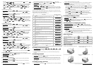
Types of Input Sensors & Temperature Range
1. Set up input sensor: Enter parameter (see “Setting up Parameters” section for details) in
“initial setting mode” and select an input sensor (see Table 1).
2. Set up temperature range: Enter parameter
and (see “Setting up Parameters”
section for details) in “initial setting mode” to set up the temperature range.
3. Set up the position of decimal point: Enter parameter
(see “Setting up Parameters” section
for details) in “operation mode”. The position of decimal point will change the temperature range.
The screen displays only 4 digits; therefore, you have to set “0” in this parameter if you wish to
display values bigger than 999 or smaller than -99. The setting will not be saved. Default = 1.
Input Sensor Type Display Range
Platinum resistance (Cu50)
-50 ~ 150°C
Platinum resistance (Ni120)
-80 ~ 300°C
Platinum resistance (Pt100)
-200 ~ 850°C
Platinum resistance (JPt100)
-20 ~ 400°C
Thermocouple TXK type
-200 ~ 800°C
Thermocouple U type
-200 ~ 500°C
Thermocouple L type
-200 ~ 850°C
Thermocouple B type
100 ~ 1,800°C
Thermocouple S type
0 ~ 1,700°C
Thermocouple R type
0 ~ 1,700°C
Thermocouple N type
-200 ~ 1,300°C
Thermocouple E type
0 ~ 600°C
Thermocouple T type
-200 ~ 400°C
Thermocouple J type
-100 ~ 1,200°C
Thermocouple K type
-200 ~ 1,300°C
Table 1
Setting up Control Output
For PID Control Application:
1. Set up 2 outputs:
Enter parameter and in “initial setting mode” (see “Setting up
Parameters” section for details). Set up one of the two parameters as or of control
output.
2. Set up control type:
Enter parameter in “initial setting mode” (see “Setting up Parameters”
section for details) and set it up as (PID) control.
3. Set up parameters:
In “regulation mode”
Parameter
:Can be set up when parameter is set as . When is set
as , the program will calculate parameters , , , and
automatically and save them.
Parameter
, and .