


Warning
Please read this instruction sheet carefully before use.
DVPAETB series is an OPEN-TYPE device and therefore should be installed in an enclosure free of airborne dust,
humidity, electric shock and vibration. The enclosure should prevent non-maintenance staff from operating the
device (e.g. key or specific tools are required to open the enclosure) in case danger and damage on the device may
occur.
DO NOT connect input AC power supply to any of the I/O terminals; otherwise serious damage may occur.. Check
all the wiring again before switching on the power, and DO NOT touch any terminal when the power is switched
on.
Introduction
DVPAETB-ID32A/OR16A extension drive board is designed for connecting to DVP32SM11N and
DVP32SN11TN, the I/O module with multiple points.
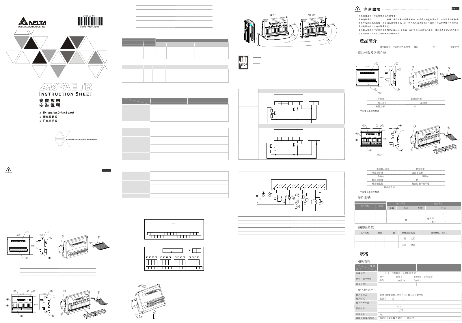
Product Profile & Outline
DVPAETB-ID32A
Unit: mm
1. 40-pin header connector 4. Bottom fastening lock
2. 36-pin input terminal 5. 40-pin IDC connection cable*1
3. DIN rail clip 6. DIN rail
*1: You can select Delta’s standard accessory DVPACAB7A10 (IDC 40P-40P 1m)
DVPAETB-OR16A
Unit: mm
ENGLISH
1. 2-PIN power input terminal 7. DIN rail clip
2. Power indicator 8. Bottom fastening lock
3. 20-pin header connector 9. 20-pin IDC connection cable*2
4. Output indicator 10. DIN rail
5. Output relay 11. Output point action indicator
6. 9-pin+11-pin output terminal
*2: You can select Delta standard accessory DVPACAB7B10 (IDC 40P-20Px2 1m)
Model Explanation
Input Unit Output Unit
Model Name Power
Points Type Points Type
DVPAETB-ID32A N/A 32
DC Type
Sink/Source
0 N/A
DVPAETB-OR16A
24V DC 0 N/A 16
Relay 250V AC/30V DC
2A/1 point, 5A/COM.
Connection Cable
Model Name Length Pins Connector Applicable PLC (accessory)
DVPACAB7A10 1m 40P-40P
IDC connector on
both sides
DVP32SM11N (DVPAETB-ID32A)
DVPACAB7B10 1m 40P-20Px2
IDC connector on
both sides
DVP32SN11TN (DVPAETB-OR16A)
Specifications
Electrical Specifications
Model
Item
DVPAETB-ID32A DVPAETB-OR16A
Insulation resistance > 5MΩ (all I/O point-to-ground: 500V DC)
Operation/storage
environment
Operation: 0 ~ 55°C (temperature), 50 ~ 95% (humidity), pollution degree 2
Storage: -25 ~ 70°C (temperature), 5 ~ 95% (humidity)
Weight (g) 166g 216g
Input Point
Type DC (There is no actual input device. Please refer to spec. of DVP32SM11N.)
Input format DC (SINK or SOURCE)
Input voltage/current 24V DC 5mA
Off → On more than 16V DC
Action level
On → Off less than 14.4V DC
Response time Approx. 10ms
Circuit isolation/operation
instruction
By internal photocoupler / LED indicators
Output Point
Type Relay-R
Current specification 2A/1point (5A/COM)
Voltage specification < 250V AC, 30V DC
75VA (inductive)
Maximum load
90W (resistive)
Response time Approx. 10ms
Installation & Wiring
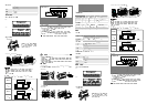
Terminals of Digital I/O Extension Unit
ID32A
X0 X2 X4 X6 X10 X12 X14 X16 X20 X22 X24 X26 X30 X32 X34 X36
X1 X3 X5 X7 X11 X13 X15 X17 X21 X23 X25 X27 X31 X33 X35 X37S/SS/S
S/SS/S
OR16A
Y1 Y2 Y3 C1 Y4 Y5 Y6 Y7 C2Y10 Y11 Y12 Y13C3Y14 Y15C0 Y0 Y14 Y15
+24VGND
Y1 Y2 Y3 Y4 Y5 Y6 Y7 Y10 Y11 Y12Y13 Y14 Y15Y0 Y14 Y15
Installation
How to install DIN rail:
Fix one side first.
Next, insert the drive board into the DIN rail and
check if the board is tightly knitted to the rail.
To uninstall the board, push up the board and pull it
out. Follow the steps as indicated in the figure.
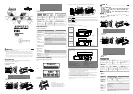
Configuration of output points in the connection of DVP32SN11TN and DVPAETB-OR16A:
Environment Notice:
DO NOT install the board in the environment with dust, smoke, metallic debris, corrosive or
flammable gas
DO NO install the board in the premise of high temperature, humidity, direct shock and vibration
DO NOT place the I/O signal wires and power supply wires in the same wiring duct or use cables
of multiple cores.
Wiring of I/O Points
Wiring of input points:
There are two types of DC inputs, SINK and SOURCE.
Wiring Loop
DC
(DC Signal IN)
SINK Mode
S/SX37X36X35X0
+24V GND
POWER SUPPLY
SINK Mode
DVPAETB-ID32A
Wiring Loop
DC
(DC Signal IN)
SOURCE Mode
S/SX37X36X35X0
+24V GND
POWER SUPPLY
SOURCE Mode
DVPAETB-ID32A
Wiring of output points:
Relay output circuit wiring
MC2MC1
9
10
C0
Y0
Y4
Y2
C2
Y3
Y5
Y1
5 2
3
7
8
1
6
7
2
5 4
MC2
MC1
Y6
Y7
8
DVPAETB-OR16A
1. Other output points 6. Varistor*3
2. Fuse 7. Inductive load
3. Reverse current protection diode*1 8. Incandescent light (resistive load)
4. Manual exclusive output*2 9. DC power supply
5. Emergency stop: Uses external switch 10. AC power supply
*1: There is no intermal protection circuit inside the output relay of DVPAETB-OR16A. Therefore, when
activating a DC inductive load, please parallelly connect it to a reverse current protection diode to extend
the life of the contact. The reverse current protection diode shall comply with the following specifications:
a. Able to endure maximum 5 ~ 10 times the amount of the load voltage.
b. Its forward current has to be bigger than the load current.
*2: The manual exclusive output uses external circuit and forms an interlock, together with the program
inside the PLC, to ensure safety protection in case of any unexpected errors.
*3: There is no internal protection circuit inside the output relay of DVPAETB-OR16A. Therefore, when
activating an AC inductive load, please parallelly connect it to a varistor (0.1uF + “100ohm to 120ohm”) to
reduce the interference in the AC load and extend the life of the contact.
Note: Please select proper safety wires. If the wires are not sufficient in long-time operation, overheating and
sparking may occur.
(OPEN TYPE) /
/
DVPAETB-ID32A/OR16A I/O DVP32SM11N DVP32SN11TN
DVPAETB-ID32A
mm
1. 40PIN 4.
2. 36PIN 5. 40PIN IDC *1
3. DIN 6. DIN
*1: DVPACAB7A10 (IDC 40P-40P 1m)
DVPAETB-OR16A
mm
1. 2PIN 7. DIN
2. 8.
3. 20PIN 9. 20PIN IDC *2
4. 10. DIN
5. 11.
6. 9PIN+11PIN
*2: DVPACAB7B10 (IDC 40P-20Px2 1m)
DVPAETB-ID32A N/A 32
DC Type
Sink/Source
0
DVPAETB-OR16A 24V DC 0
16
Relay 250V AC/30V DC
2A/1 5A/COM
PIN
DVPACAB7A10 1m 40P-40P IDC DVP32SM11N (DVPAETB-ID32A)
DVPACAB7B10 1m 40P-20Px2 IDC DVP32SN11TN (DVPAETB-OR16A)
DVPAETB-ID32A DVPAETB-OR16A
5 MΩ 500V DC
0 ~ 55°C 50 ~ 95% 2
-25 ~ 70°C 5 ~ 95%
(g)
166g 216g
DVP32SM11N
SINK SOURCE
24V DC 5mA
Off → On 16V DC
On → Off 14.4V DC
10ms
/ / LED