


Warning
Always read this instruction sheet thoroughly before using DVP-ES/EX digital I/O extension unit.
This is an OPEN TYPE extension unit. The extension unit should be kept in an enclosure away from airborne, dust, high
humidity, electric shock risk and vibration. Also, it is equipped with protective methods such as special tools or keys to open the
enclosure, so as to avoid the hazard to users and damage the extension unit.
DO NOT connect AC main circuit power supply to any of the input/output terminals, as it will damage the extension unit. Check
all the wiring prior to power up.
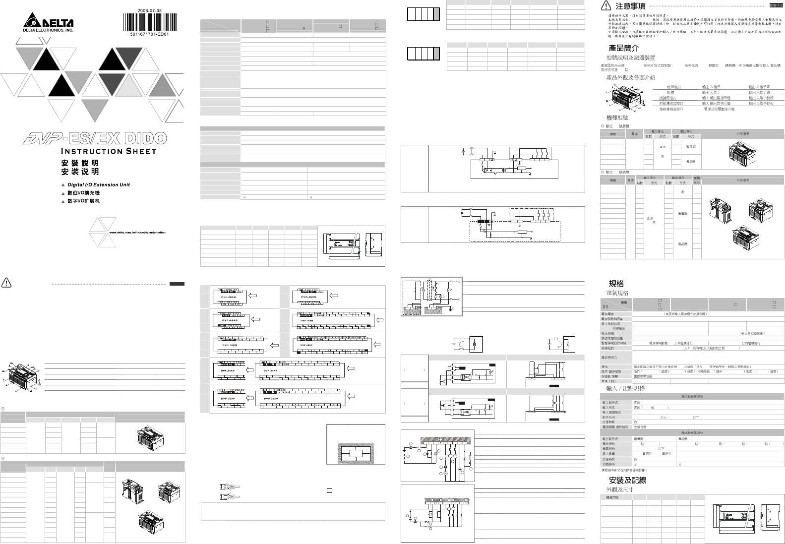
Introduction
Model Name Explanation & Peripherals
Thank you for choosing Delta DVP-ES/EX series PLC. The main processing unit offers 8 ~ 32 points and the maximum
input/output can be extended up to 128 points individually.
Product Profile & Outline
DVP-ES/EX Series Model
Digital I/O extension unit -- 00
Input/output spec.
Model name
Power Point Type Point Type
Profile reference
DVP24XN00R
0 24
DVP24XP00R
16 8
DVP32XP00R
16 16
Relay
DVP24XP00T
16 8
DVP24XN00T
0 24
DVP32XP00T
100 ~ 240V
AC
16
DC SINK or
SOURCE
16
Transistor
Digital I/O extension unit -- 11
Input/output spec.
Model name
Power Point
Type Point
Type
Profile
Profile reference
DVP08XM11N
8 0
DVP16XM11N
16 0
N/A
DVP08XN11R
0 8
DVP16XN11R
0 16
DVP24XN11R
0 24
DVP08XP11R
4 4
DVP24XP11R
16 8
DVP32XP11R
16 16
Relay
DVP08XN11T
0 8
DVP16XN11T
0 16
DVP24XN11T
0 24
DVP08XP11T
4 4
DVP24XP11T
16 8
DVP32XP11T
24V DC
16
DC SINK or
SOURCE
16
Transistor
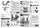
1. DIN rail clip 8. Input/output indicators
2. DIN rail (35mm) 9. Input/output indicators
3. Direct mounting holes 10. Status indicators: POWER, RUN and ERROR
4. Mounting hole for MPU or previous extension unit
11. Input/output terminal cover
5. Mounting hole for next extension unit 12. Input/output terminal cover
6. Input/output terminals 13. Input/output terminal nameplate panel
7. Input/output terminals 14. Input/output terminal nameplate panel
EN
G
LISH
Specifications
Electrical Specification
Model
Item
DVP08XN11
DVP08XP11
DVP16XN11
DVP08XM11N
DVP16XM11
DVP24XP00
DVP24XN00
DVP32XP00
Power supply voltage 24V DC (-15% ~ 20%) (24V DC input polarity) 100 ~ 240V AC (-15% ~ 20%) 50/60Hz ± 5%
Fuse 2A/250V AC
Power consumption (MAX)
5W 25VA 30VA
24V DC supply current -- 400mA --
Power protection -- 24V DC output with short-circuit protection
Voltage withstand 1,500V AC (primary-secondary), 1,500V AC (primary-PE), 500V AC (secondary-PE)
Maximum power loss time 5ms or less 10ms or less
Insulation resistance > 5MΩ (between all input/output and earth)
Noise immunity
ESD (IEC 61131-2, IEC 61000-4-2): 8KV Air Discharge
EFT (IEC 61131-2, IEC 61000-4-4): Power Line: 2KV, Digital I/O: 1KV,
Analog & Communication I/O: 1KV
RS (IEC 61131-2, IEC 61000-4-3): 26MHz ~ 1GHz, 10V/m
Grounding
The diameter of grounding wire cannot be smaller than the wire diameter of terminals L and N (All DVP
units should be grounded directly to the ground pole)
Environment
Operation: 0°C ~ 55°C (temperature), 50 ~ 95% (humidity), Pollution degree 2;
Storage: -25°C ~ 70°C (temperature), 5 ~ 95% (humidity)
Vibration/shock resistance
Standard: IEC 61131-2, IEC 68-2-6 (TEST Fc)/IEC 61131-2 & IEC 68-2-27 (TEST Ea)
weight (g) 170/165 160/270 600/580
I/O Terminal Specification
Electrical specification of input point
Input point type DC
Input type DC (SINK or SOURCE)
Input current 24V DC 5mA
Active level Off → On, above 16.5V DC, On → Off, below 8V DC
Reaction time About 20ms
Circuit isolation/operation
indicator
Optocoupler/LED On
Electrical specification of output point
Output point type Relay-R Transistor-T
Current spec. 2A/1point (5A/COM)
55°C 0.1A/1point, 50°C 0.15A/1point,
45°C 0.2A/1point, 40°C 0.3A/1point (2A/COM)
Voltage spec. Below 250V AC, 30V DC 30V DC
Maximum load 75VA (inductive), 90W (resistive) 9W
Reaction time About 10ms Off → On 15us On → Off 25us
Switching frequency* 1Hz 1kHz
*The actual frequency will be affected by the scan period.
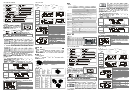
Installation and Wiring
Outline & Dimension
Model name (mm) H H1 W W1 W2
DVP08XM11N 100 95 42 37.5 82
DVP16XM11N 100 95 104 99 82
DVP08XN11R/T 100 95 42 37.5 82
DVP16XN11R/T 100 95 155 150 82
DVP24XN11R/T 100 95 155 150 82
DVP08XP11R/T 100 95 42 37.5 82
DVP24XP11R/T 100 95 155 150 82
DVP32XP11R/T 100 95 155 150 82
W2
H
W1
DVP
H
1
W
Terminal Wiring
08XM
11
( DC Pow er IN )
08XN
11
( DC Power IN )
08XP
11
( DC Power IN )
16XN
Y0 Y1 Y2 Y3
Y4 Y 5
C1
C0 C2 C3 C4 C5
C11
C12
C13
Y11
Y1 2
Y1 3
Y1 4
Y1 5
Y1 6
Y1 7
C14
C15
C16
C17
11
( DC Powe r IN )
Y6 Y 7
C6 C7
Y1 0
C10
16XM
X1
11
X11
X0
X7
X16X17
X10
( DC Po wer I N )
S/S
24G
X2 X 3 X4 X5 X6
X12X 13X14X15
24XP
X1
C3
Y3 Y4
11
X0 X2 X3 X4 X5 X6 X7
( DC Power IN, DC Sig nal IN )
Y5 Y6 Y7
C4 C5 C6 C7
Y0 Y1
C0 C1
Y2
C2
24XN
Y4Y3Y2Y1Y0
C10
Y12
Y13
Y16
Y17
Y15Y14Y11
( AC Power IN )( DC Power IN )
Y10
C10
Y11Y12 Y14
C11C13
11
C11 C12C13
Y11
C15C14 Y23
Y20Y21 Y22
C0 C1 C 2 C3 C4
00
Y7
Y6Y5
C16C17
Y24Y25 Y26
Y27
C5 C6
C7
32XP
Y7
Y6
Y5Y4
Y3Y2
Y1Y0
Y12Y1 3 Y16
( AC Power IN, DC Signal IN )( DC Power IN, DC Signal IN )
Y0
C0
11
C0
C1
C2
C3
Y1
Y2 Y3
Y4
Y10Y11 Y14Y15
X10X11 X12X1 3 X14X15X1 6
X0 X1 X2 X3 X4 X5
00
Y17
X17
X6 X7
Mounting Arrangements & Wiring Notes
DIN Rail Installation:
The DVP-PLC (or extension unit) can be secured to a cabinet by using the DIN rail
that is 35mm high with a depth of 7.5mm. When mounting the PLC (or extension
unit) on the DIN rail, be sure to use the end bracket to stop any side-to-side
motion of the PLC (or extension unit), thus to reduce the chance of the wires being
pulled loose. On the bottom of the PLC is a small retaining clip. To secure the PLC
to the DIN rail, place it onto the rail and gently push up on the clip. To remove it,
pull down on the retaining clip and gently pull the PLC away from the DIN rail.
For heat dissipation. Make sure to
provide a minimum clearance of
50mm between the unit and all sides
of the cabinet (as shown below).
DVP MPU
> 50mm
> 50mm
> 50mm
> 50mm
Direct Mounting:
Use the specified dimensions and install with M4 screws.
Wiring:
Below 6.8 mm
To suit M3.5 screw terminal
Below 6.8 mm
1.
Please use O-type or Y-type terminals for I
/O wiring terminals. The specification for
the terminals is as shown on the left. PLC terminal screws should be tightened to
between 5 ~ 8 kg-cm (4.3 ~ 6.9 in-lbs). Use copper conductor only, 60°C/75°C.
2.
DO NOT wire to the No Function terminals. • .
3.
After completing wiring, please remove the label which is used to obstruct the
metallic particles on the ventilation hole for well heat dissipation.
Environment
1.
DO NOT store the PLC in an airborne dust, smoky, metallic particles, corrosive or flammable gases.
2.
DO NOT store the PLC in a location where temperatures and humidity will exceed specification or in
a location where vibration and shock will exceed specification.
3.
I/O signal wires or power supply should not run through the same multi-wire cable or conduit.
I/O Point Serial Sequence
1.
When using MPU with points less than 32 to connect extension unit, the input number of the 1
st
extension unit will be
started from X20 in sequence and the output number will be started from Y20 in sequence. Please refer to the following
example for detail:
PLC Model Input points
Output points
Input number Output number
MPU 14ES/20EX/32ES
8/8/16 6/6/16
X0 ~ X7/X0 ~ X17
Y0 ~ Y5/Y0 ~ Y17
EXT1 32XP00T 16 16 X20 ~ X37 Y20 ~ Y37
EXT2 24XP11R 16 8
X40 ~ X57 Y40 ~ Y47
EXT3 08XN11R 0 8 - Y50 ~ Y57
System application example 1:
MPU EXT1 EXT2 EXT3EXT4
EXT4 08XP11R 4 4 X60 ~ X63 Y60 ~ Y63
2.
When using MPU with points 60 to connect extension unit, the input number of the 1
st
extension unit will be started from
X50 in sequence and the output number will be started from Y30 in sequence. Please refer to the following example for
detail:
PLC Model Input points
Output points
Input number Output number
MPU 60ES 36 24 X0 ~ X43 Y0 ~ Y27
EXT1 32XP00T 16 16 X50 ~ X67 Y30 ~ Y47
EXT2 24XP11R 16 8 X70 ~ X107 Y50 ~ Y57
EXT3 08XN11R 0 8 - Y60 ~ Y67
System application example 2:
MPU EXT1 EXT2 EXT3EXT4
EXT4 08XP11R 4 4 X110 ~ X113 Y70 ~ Y73
In the system application example 1, if the input/output points of the 1st MPU are less than 16, its input/output will be
defined as 16 and thus there will be no corresponding input/output points for higher number.
In the system application example 2, if the input points of 1st MPU are 36, its input will be defined as 40 and there will be
no corresponding input points for the number 44 ~ 47.
In the system application example 1 and 2, the 4
th
extension unit 08XP11R will be defined as 8 input/output points and
there will be no corresponding input/output points for the 4 higher numbers. In order to continue the input/output number,
place the extension unit at last if the extension unit is with empty input/output numbers.
Power Input Wiring and Specification
The power inputs for DVP-ES/EX series PLC are AC and DC inputs. Please pay particular attention to the following notes:
1.
Connect the AC input (100V ~ 240V) to terminals L and N. Any 110V AC or 220V AC connected to the +24V terminal or
input points will permanently damage the PLC.
2.
The AC power inputs for the MPU and the I/O Extension Unit should be ON or OFF at the same time.
3.
Please use wires of 1.6mm or above for the grounding of the MPU.
4.
If the power-cut time is less than 10ms, the PLC still operates unaffectedly. If the power-cut time is too long or the power
voltage drops, the PLC will stop operation and all outputs will be off. Once power is on again, the PLC will resume
automatically. (There are latched auxiliary relays and registers inside of the PLC, please be aware when programming.)
AC input type
S/S X0
X1
X2
24GN
L
DC/DC
2.0A
5V
100~240VAC
The +24V supply output is rated at 0.4A as max. from MPU. DO NOT connect external power supply
to this termianl. Moreover, it takes 5 ~ 7mA to drive each input point, so total of 100mA is needed for
16 input points. As a result, the output load of +24V should not exceed 300mA.
5.
When DC voltage is supplied to the PLC, ensure the power is at terminals 24V DC and 0V (power range is 20.4V DC ~
26.4V DC). When the voltage is lower than 17.5V DC, PLC will stop operating, all outputs will turn OFF and the ERROR
LED will flash rapidly.
DC input type
S/S
X0
X1 X2
+24V 24G
24V DC
DC/DC
2.5A
5V
20VDC~26VDC
Safety Wiring
Since the PLC is in control of numerous devices, operation of either one device could affect the operation of other devices;
therefore, the breakdown of either one device would consequently be detrimental to the whole auto control system, and
danger will thus be resulted. Please use the recommended wiring below for the power input:
Power supply for AC loads.
Fuse for circuit protection (3A limit)
Power on pilot indicator
Emergency stop: a manual stop button is provided for emergency to disconnect
system power.
Circuit isolation device (system power disconnect): use electromagnetic contactor
and the relay to be the isolation unit of the power circuit to prevent the possible
instability of the system when the power is supplied on and off.
DVP PLC MPU (main processing unit).
Grounding resistance: below 100Ω
OV
24VDC
MC
MC
N
L
1
1
2
3
4
5
66
8
Guard
Limit
Power supply: AC: 100 ~ 240V AC, 50/60Hz. DC: 24V DC
Input/Output Point Wiring
Input Point Wiring
There are SINK and SOURCE types for the input signal of the input point with DC input. Definition as follows:
Sink = Current flows into
common terminal S/S
S/S
X0
Sinking
Source = Current flows out of
common terminal S/S
S/S
X0
Sourcing
Input point loop equivalent circuit Wiring loop
DC type
DC Signal IN
SINK mode
+24V
24G
S/S
X0
24 VDC
SIN K
+5V
+24V24G
Sink Type
X1
X2S/S
X0
Input point loop equivalent circuit Wiring loop
DC type
DC Signal IN
SOURCE mode
+24V
24G
S/S
X0
24VD C
SOUR CE
+5V
+24V24G
Source Type
X1X2
S/SX0
Output Point Wiring
Surge absorbing diode: increase relay contact life
Emergency stop: use an external switch.
Fuse: use the fuse with 5 ~ 10A at the common end of the output contact to
protect the output circuit.
Surge absorber: reduces noise on AC inductive loads
Unused terminal: DO NOT connect.
DC supply
Indicator: neon indicator.
AC supply
Incandescent lamp (resistive loading)
Relay output wiring
C0 Y0 Y1 C1 Y4 Y5 Y6 Y7
5
MC1
MC2
2
6
3
1
9
10
7
4
3
8
2
Mutually exclusive outputs: use external hardware interlock and those in the
PLC program to secure any emergent errors to be with safety protection.
DC supply
Emergency stop
Circuit protection fuse
As all outputs of the transistor modules are Open Collectors, if the setting of
Y0 is pulse train output (use PLSY instruction), its pull-up resistor must
remain an output current of greater than 0.1A for normal operation of the
transistor modules.
As all outputs of the transistor modules are Open Collectors, if the setting of
Y1 is pulse train output (use PWM instruction), its pull-up resistor must
remain an output current of greater than 0.1A for normal operation of the
transistor modules.
Mutually exclusive outputs: use external hardware interlock and those in the
PLC program to secure any emergent errors to be with safety protection.
Transistor output wiring
5
MC1
MC2
2
3
1
C0 Y0
Y1C1
Y4
Y5
Y6
Y7
4
6 7
6
3
Unused terminal
(OPEN TYPE)
DVP-ES/EX ES/EX 8 ~ 32 I/O /
128
1.
DIN 6. / 11. /
2.
DIN (35mm) 7. / 12. /
3.
8. / 13. /
4.
9. / 14. /
5.
10.
I/O -- 00
DVP24XN00R 0 24
DVP24XP00R 16 8
DVP32XP00R 16 16
DVP24XP00T 16 8
DVP24XN00T 0 24
DVP32XP00T
100 ~ 240V
AC
16
SINK
SOURCE
16
I/O -- 11
DVP08XM11N 8 0
DVP16XM11N 16 0
DVP08XN11R 0 8
DVP16XN11R 0 16
DVP24XN11R 0 24
DVP08XP11R 4 4
DVP24XP11R 16 8
DVP32XP11R 16 16
DVP08XN11T 0 8
DVP16XN11T 0 16
DVP24XN11T 0 24
DVP08XP11T 4 4
DVP24XP11T 16 8
DVP32XP11T
24V
DC
16
SINK
SOURCE
16
DVP08XN11
DVP08XP11
DVP16XN11
DVP08XM11N
DVP16XM11N
DVP24XP00
DVP24XN00
DVP32XP00
24V DC (-15% ~ 20%)
100 ~ 240V AC (-15% ~ 20%) 50/60Hz ± 5%
2A/250V AC
5W 25VA 30VA
24V DC -- 400mA --
-- 24V DC
1,500V AC (primary-secondary), 1,500V AC (primary-PE), 500V AC (secondary-PE)
5ms 10ms
5MΩ / 500V DC
ESD (IEC 61131-2, IEC 61000-4-2): 8KV Air Discharge
EFT (IEC 61131-2, IEC 61000-4-4): Power Line: 2KV, Digital I/O: 1KV,
Analog & Communication I/O: 1KV, RS (IEC 61131-2, IEC 61000-4-3): 26MHz ~ 1GHz, 10V/m
L, N PLC
/ 0
°C
~ 55
°C
50 ~ 95% 2 -25
°C
~ 70
°C
5 ~ 95%
/ IEC 61131-2, IEC 68-2-6 (TEST Fc)/IEC 61131-2 & IEC 68-2-27 (TEST Ea)
(g) 170/165 160/270 600/580
SINK SOURCE
24V DC 5mA
Off → On 16.5V DC On → Off 8V DC
20ms
/ /LED On
-R -T
2A/1 5A/COM 55
°C
0.1A/1 50
°C
0.15A/1 45
°C
0.2A/1 40
°C
0.3A/1 2A/COM
250V AC, 30V DC 30V DC
75VA ( ), 90W ( ) 9W
10ms Off → On 15us On → Off 25us
* 1Hz 1kHz
*
(mm) H H1 W W1 W2
DVP08XM11N 100 95 42 37.5 82
DVP16XM11 N 100 95 104 99 82
DVP08XN11R/T 100 95 42 37.5 82
DVP16XN11R/T 100 95 155 150 82
DVP24XN11R/T 100 95 155 150 82
DVP08XP11R/T 100 95 42 37.5 82
DVP24XP11R/T 100 95 155 150 82
DVP32XP11R/T 100 95 155 150 82
W2
H
W1
DVP
H1
W