


Warning
This Instruction Sheet only provides descriptions for electrical specifications, general specifications, installation &
wiring. Other detail infromation about programming and intructions is compatible with SV series; please see PLC
Application Manual. For more information about the optional peripherals, please see individual product instuction
shee or “DVP-PLC Application Manual: Special module”.
This is an OPEN TYPE PLC. The PLC should be kept in an enclosure away from airborne dust, humidity, electric
shock risk and vibration. Also, it is equipped with protective methods such as some special tools or keys to open the
enclosure, in order to prevent hazard to users or damage the PLC.
Do NOT connect the AC main circuit power supply to any of the input/output terminals, or it may damage the PLC.
Check all the wiring prior to power up. To prevent any electromagnetic noise, make sure the PLC is properly
grounded . Do NOT touch terminals when power on.
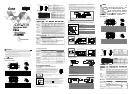
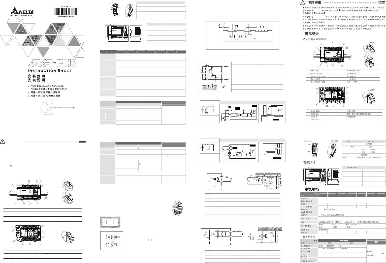
Introduction
Product Profile & Outline
1
2
3
5
9 4
9
6
10
5
4
7
8
Open COM1 Cover
Communication port cover
Extension module connection port cover
I/O terminal cover
Input indicator
Function card/memory card cover
Output indicator
I/O terminals
DIN rail clip
I/O terminal No.
DIN rail (35mm)
3
1
2
6
7
1
2
5
4
8
Open COM2 cover
Mounting screw
Memory card port
Direct mounting hole
POWER/RUN/BAT.LOW/ERROR indicator
Battery socket
Extension module connection port
Function card mounting hole
ENGLISH
Removable Terminal Block
COM 2 (RS-485)
RUN / STOP SWITC H
VR 0 VR 1
COM 1 (RS-232)
Battery
Remove RS-485
terminal
Part Description
COM2 (RS-485) For both master & slave modes
RUN/STOP switch PLC RUN/STOP control
VR0 Enable M1178/corresponding value of D1178
VR1 Enable M1179/corresponding value of D1179
COM1 (RS-232) For slave mode
Battery Shall be changed within 1 min.
Dimension
4
.
6
X
2
W
W1
80.0
9
0
.
0
82.2
Model W (mm) W1 (mm)
DVP16EH00R2/T2 113 103
DVP20EH00R2/T2 113 103
DVP32EH00R2/T2 143.5 133.5
DVP40EH00R2/T2 158.8 153.8
DVP48EH00R2/T2 174 164
DVP64EH00R2/T2 212 202
DVP80EH00R2/T2 276 266
Specifications
Model
Item
16EH00
2
20EH00
2
32EH00
2
40EH00
2
48EH00
2
64EH00
2
80EH00
2
Power supply
voltage
100 ~ 240V AC (-15% ~ 10%); 50/60Hz ± 5%
Fuse capacity 2A/250V AC
Power consumption
50VA 50VA 60VA 60VA 60VA 80VA 80VA
DC24V current
supply
500mA 500mA 500mA 500mA 500mA 500mA 500mA
Power protection DC24V; output short-circuited
Withstand voltage 1,500V AC (Primary-Secondary); 1,500V AC (Primary-PE); 500V AC (Secondary-PE)
Insulation
resistance
> 5 MΩ (all I/O point-to-ground: 500V DC)
Noise immunity
ESD: 8KV Air Discharge; EFT: Power Line: 2KV, Digital I/O: 1KV, Analog & Communication I/O:
250V; Damped-Oscillatory Wave: Power Line: 1KV, Digital I/O: 1KV, RS: 26MHz ~ 1GHz, 10V/m
Earth
The diameter of grounding wire shall not be less than that of L, N terminal of the power. (When
many PLCs are in use at the same time, please make sure every PLC is properly grounded.)
Operation/storage
Operation: 0ºC ~ 55ºC (temperature); 50 ~ 95% (humidity); pollution degree 2
Storage: -40 ºC ~ 70 ºC (temperature); 5 ~ 95% (humidity)
Vibration/shock
immunity
International standards: IEC61131-2, IEC 68-2-6 (TEST Fc)/IEC61131-2 & IEC 68-2-27 (TEST
Ea)
Weight (g) 500/480 520/500 652/612 710/675 748/688 836/756 948/848
Input Point Specification
24VDC single common port input
Spec.
Items
Low speed High speed (200KHz)
Note
Input wiring type Change wiring from S/S to SINK or SOURCE
Input indicator LED display; light on = ON, light off = OFF
Input voltage 24VDC
Off On
X0 ~ X7, X12, X13, X16, X17, X20 ~ X47: > 18.5V DC
X10, X11, X14, X15: > 16.5V DC
Active
Level
On Off X0 ~ X47: < 8V DC
Response time/
noise immunity
10ms 0.5us
Input point X0 ~ X7, X10 ~ X17
can conduct 10 ~ 60ms digital
filter adjustment
Output Point Specification
Single common port transistor output
Spec.
Items
Low speed High speed*
Single common port relay
output
Max. frequency 10KHz 200KHz Load ON/OFF control
Output indicator LED display; light on = ON, light off = OFF
Min. load - 2mA/DC power supply
Working voltage 5 ~ 30VDC
250V AC, 30V DC
Insulation Photocoupler isolation Magnetic isolation
Current
specification
0.3A/1 point @ 40ºC
<1KHz, 0.3A/1 point @ 40°C
1KHz, 30mA/1 point @ 40°C
2A/1 point (5A/COM)
75VA (conductive), 90W
(resistive)
Off On: 20us
Max. output delay
time
On Off: 30us
0.2us 10ms
Over-current
protection
N/A
Mechanical life N/A 2×10
7
times (without load)
Electrical life N/A
1.5×10
5
times (5A 30V DC);
5×10
5
times (3A 120V AC);
3×10
4
times (5A 250V AC)
*High-speed output points (Y0, Y2) are only in DVP20EH2 and DVP32EH2; high-speed output points (Y0, Y1, Y2, Y3, Y4, Y6) are
only in DVP40EH2.
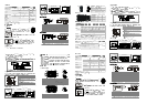
Installation & Wiring
3.1 PLC Mounting Arrangements and Wiring Notes
How to install DIN rail:
DVP-PLC can be secured to a cabinet by using the DIN rail of 35mm in height and
7.5mm in depth. When mounting PLC to DIN rail, be sure to use the end bracket to stop
any side-to-side movement of PLC and reduce the chance of wires being loosen. A small
retaining clip is at the bottom of PLC. To secure PLC to DIN rail, place the clip onto the
rail and gently push it up. To remove it, pull the retaining clip down and gently remove
PLC from DIN rail, as shown in the figure.
How to screw: Please use M4 screw according to the dimension of the product.
DV P MPU
> 50mm> 50mm
> 50mm
> 50mm
Please install PLC in an enclosure with sufficient space around it to allow heat
dissipation as shown in the figure.
Wiring:
To suit M3.5 screw terminals
Below 6.2
Below 6.2
1. Use O-type or Y-type terminal. See the figure in the left hand side for its
specification. PLC terminal screws should be tightened to 5 ~ 8 kg-cm (4.3 ~
6.9 in-Ibs) and please use only 60/75ºC copper conductor.
2. DO NOT wire empty terminal • . DO NOT place the input signal cable and
output power cable in the same wiring circuit.
3. DO NOT drop tiny metallic conductor into the PLC while screwing and wiring.
Tear off the sticker on the heat dissipation hole for preventing alien
substances from dropping in, to ensure normal heat dissipation of the PLC.
3.2 Wiring Notes
Power Input Wiring
The power input of DVP-EH series is AC. When operating the PLC, please make sure that:
1.
The input voltage should be current and its range should be 100 ~ 240V
AC.
The
power should be
connected to L and N terminals. Wiring AC110V or AC220V to +24V terminal or input terminal will result in
serious damage on the PLC.
2. The AC power input for PLC MPU and I/O extension modules should be ON or OFF at the same time.
3. Use wires of 1.6mm (or longer) for the grounding of PLC MPU. The power shutdown of less than 10 ms will
not affect the operation of the PLC. However, power shutdown time that is too long or the drop of power
voltage will stop the operation of the PLC and all outputs will go OFF. When the power supply turns normal
again, the PLC will automatically return to its operation. Please be aware of the latched auxiliary relays and
registers inside the PLC when programming.
AC Power Input
L N
2.0 A
DC/DC
+5V
+24V
24G S/S
X0 X1 X2
100~240VAC
0.5A is the maximum power supply for +24V power supply output terminal. DO NOT connect other
external power supplies to this terminal. Every input terminal requires 6 ~ 7mA to be driven; e.g. the
16-point input will require approximately 100mA. Therefore, +24V cannot give output to extermal load
that is more than 400mA.
Safety Wiring
Since a PLC controls many devices, actions of any device may affect actions of other devices, and the
breakdown of any one device may cause the breakdown of the whole auto-control system and danger.
Therefore, we suggest you wire a protection circuit at the power input terminal, as shown in the figure below.
AC power supply load
Power circuit protection fuse (3A
Power indicator
Emergency stop
This button can cut off the system power supply when accidental
emergency takes place.
System circuit isolation device
The device is made of electromagnetic contactor and relay as the
switch to prevent the instability of system when the power is
intermittently supplied.
DVP-PLC (main processing unit)
Earth
MC
MC
NL
1
1
2
3
4
5
6
8
G uard
Li mit
MC
Power supply AC: 100 ~ 240V AC
Input Point Wiring
There are two types of DC inputs, SINK and SOURCE.
Input point loop equivalent circuit Wiring loop
DC Signal IN
S/S
X0
Sinking
SINK mode
(common port for current
input S/S)
24VDC
24G
X0
S/S
+24V
SINK
+5V
24G S/S X0 X1 X2+24V
Sink Type
Input point loop equivalent circuit Wiring loop
DC Signal IN
S/S
X0
Sourcing
SOURCE mode
(common port for current
output S/S)
24VDC
24G
X0
S/S
+24V
SOURCE
+5V
24G S/S X0 X1 X2+24V
Source Type
Output Point Wiring
Relay (R) contact circuit wiring
Y0
RY
LED
C0
LOAD
POWER
DVP-**-**-**-R
RELAY OUTPUT
2
3
1
5
C0 Y0 Y1 C1 Y3 Y4
C2
Y6 Y7
4
MC1
MC2
7
10
3
2
8
9
6
Flywheel diode: To extend the life span of contact
Emergency stop: Uses external switch
Fuse: Uses 5 ~ 10A fuse at the common port of output contacts to protect the output circuit.
Varistor: To reduce the interference on AC load
Empty terminal: not in use
DC power supply
Neon indicator
AC power supply
Incandescent light (resistive load)
Manually exclusive output: Uses external circuit and forms an interlock, together with the
PLC internal
program, to ensure safety protection in case of any unexpected errors.
Transistor (T) contact circuit wiring
Y0
LED
C0
TRANSISTOR OUTPUT
LOAD
DVP-**-**-**-T
< 0 .5A
MC1
M C2
2
3
1
C0 Y0 Y1 C1 Y4 Y5 Y 6 Y7
5
4
5
3
4
DC power supply
Emergency stop
Circuit protection fuse
Flywheel diode + inductive load
Manually exclusive output: Uses external circuit and forms an interlock, together with the
PLC internal
program, to ensure safety protection in case of any unexpected errors.
SV
DVP-PLC DVP-PLC
(OPEN TYPE) /
1
2
3
5
9 4
9
6
10
5
4
7
8
COM1
DIN
DIN (35mm)
3
1
2
6
7
1
2
5
4
8
COM2
COM 2 (RS-485)
RUN / S TOP
VR 0
VR 1
COM 1 (RS-232)
RS-485
COM2 (RS-485)
Master/Slave
RUN/STOP PLC RUN/STOP
VR0 M1178 /D1178
VR1
M1179 /D1179
COM1 (RS-232)
Slave
1
4
.
6
X
2
W
W1
80.0
9
0
.
0
82.2
W (mm) W1 (mm)
DVP16EH00R2/T2 113 103
DVP20EH00R2/T2 113 103
DVP32EH00R2/T2 143.5 133.5
DVP40EH00R2/T2 158.8 153.8
DVP48EH00R2/T2 174 164
DVP64EH00R2/T2 212 202
DVP80EH00R2/T2 276 266
16EH00
2
20EH00
2
32EH00
2
40EH00
2
48EH00
2
64EH00
2
80EH00
2
100 ~ 240V AC (-15% ~ 10%); 50/60Hz ± 5%
2A/250V AC
50VA 50VA 60VA 60VA 60VA 80VA 80VA
DC24V
500mA 500mA 500mA 500mA 500mA 500mA 500mA
DC24V
1,500V AC (Primary-Secondary); 1,500V AC (Primary-PE); 500V AC (Secondary-PE)
5 M ( / 500VDC)
ESD: 8KV Air Discharge; EFT: Power Line: 2KV, Digital I/O: 1KV, Analog & Communication I/O:
250V; Damped-Oscillatory Wave: Power Line: 1KV, Digital I/O: 1KV, RS: 26MHz ~ 1GHz, 10V/m
L, N PLC
/
0°C ~55°C 50 ~ 95% 2
-40°C ~70°C 5 ~ 95%
/ IEC61131-2, IEC 68-2-6 (TEST Fc)/IEC61131-2 & IEC 68-2-27 (TEST Ea)
( ), (g)
500/480 520/500 652/612 710/675 748/688 836/756 948/848
24V DC
200KHz
S/S SINK SOURCE
LED ON OFF
24V DC
Off On
X0 ~ X7, X12, X13, X16, X17, X20 ~ X47: > 18.5V DC
X10, X11, X14, X15: > 16.5V DC
On Off X0~X47: < 8V DC
/ 10 ms 0.5us
X0 ~ X7 X10 ~
X17 10 ~ 60 ms