


Warning
This Instruction Sheet only provides descriptions for electrical specifications, general specifications, installation &
wiring. Other detail infromation about programming and intructions is compatible with SA/SX/SC series; please see
PLC Application Manual. For more information about the optional peripherals, please see individual product
instuction shee or “DVP-PLC Application Manual: Special module”.
This is an OPEN TYPE PLC. The PLC should be kept in an enclosure away from airborne dust, humidity, electric
shock risk and vibration. Also, it is equipped with protective methods such as some special tools or keys to open the
enclosure, in order to prevent hazard to users or damage the PLC.
Do NOT connect the AC main circuit power supply to any of the input/output terminals, or it may damage the PLC.
Check all the wiring prior to power up. To prevent any electromagnetic noise, make sure the PLC is properly
grounded . Do NOT touch terminals when power on.
Introduction
Thank you for choosing DELTA’s PLC DVP series. The DVP-SA series has a 12-points (8 input points + 4
outputs) PLC main processing unit with multiple instructions for use. It also has an 8K Steps program memory
to connect to every SA/SX/SC series extension unit, including digital I/O (Maximum 128 inpu/128 output
extension points), analog module, etc. for various applications. Its power unit is separated from the MPU for
better space utilization and easier installation.
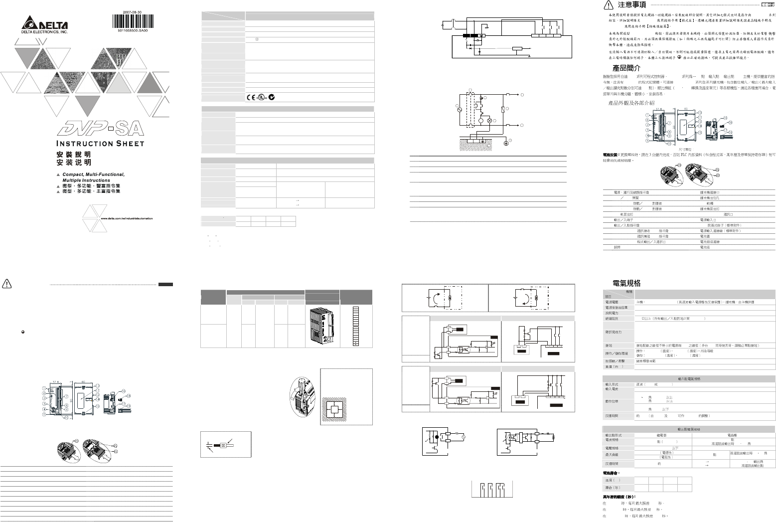
Product Profile and Outline
Unit: mm
Battery replacement: Battery replacement must be finished within 3 minutes, or the internal data of the PLC
(including the program area, RTC and latched registers) could be lost or destroyed.
1 Status indicator: POWER, RUN, ERROR, BAT.LOW
12
Extension port
2 RUN/STOP switch 13
Mounting hold of the extension unit
3 VR0: Start-up by M1178/D1178 corresponding value
14
DIN rail (35mm)
4 VR1: Start-up by M1179/D1179 corresponding value
15
Extension unit clip
5 DIN rail clip 16
COM2 (RS-485) communication port
6 I/O terminals 17
DC Power input
7 I/O point indicators 18
2 pin removable terminal (standard accessory)
8 COM1 (RS-232) (Rx) indicator 19
Power input cable (standard accessory)
9 COM2 (RS-485) (Tx) indicator 20
Battery cover
10
COM1 (RS-232) port 21
Battery socket connection
11
Nameplate 22
Battery mount
ENGLISH
Specifications
Model
Item
DVP12SA11R/T
Power supply voltage
MPU: 24V DC (-15% ~ 20%) (with DC input reverse polarity protection)
Fuse
2A / 250V AC
Power consumption
3.5W
Insulation resistance
> 5M at 500V DC (between all inputs / outputs and earth)
Noise immunity
ESD: 8KV Air Discharge
EFT: Power Line: 2KV, Digital I/O: 1KV, Analog & Communication I/O: 250V
Damped-Oscillatory Wave: Power Line: 1KV, Digital I/O: 1KV
RS: 26MHz ~ 1GHz, 10V/m
Grounding
The diameter of grounding wire cannot be smaller than the wire diameter of terminals L
and N (All DVP units should be grounded
directly to the ground pole).
Environment
Operation: 0°C ~ 55°C (temperature), 50 ~ 95% (humidity), pollution degree 2
Storage: -25°C ~ 70°C (temperature), 5 ~ 95% (humidity)
Vibration/shock resistance
Standard: IEC61131-2, IEC 68-2-6 (TEST Fc)/IEC61131-2 & IEC 68-2-27 (TEST Ea)
Weight (approx. g)
158
Certificates
Input Point Electrical Specification
Input type DC (SINK or SOURCE)
Input current 24V DC 5mA
Off → On,
X0, X1, 18.5V DC and above
X2 ~ X7, 16.5V DC and above
Active level
On → Off,
X0 ~ X7, below 8 V DC
Response time About 10ms (an adjustment range of 0 ~ 20ms could be selected through D1020 and D1021)
Output Point Electrical Specification
Output type Relay-R Transistor-T
Current specification
1.5A/1 point (5A/COM)
0.3A/1 point @ 40°C; When the output of Y0 and Y1 is high-speed
pulse, Y0 and Y1 = 30mA
Voltage specification Below 250V AC, 30V DC
30V DC
75VA (inductive)
Maximum loading
90W (resistive)
9W/1 point
When the output of Y0 and Y1 is
high-speed pulse, Y0 and
Y1 = 0.9W (Y0 = 32KHz, Y1 =
10KHz)
Response time About 10ms
Off On 20us
On Off 30us
Y0 and Y1 are specified points
for high-speed pulse
Battery life:
Temperature (C)
0 25 50 70
Life (year) 9 8 6 5
Precision of calendar timer:
At 0 C/32F, less than -117 seconds error per month.
At 25C/77 F, less than 52 seconds error per month.
At 55C/131 F, less than -132 seconds error per month.
Model Name & I/O Configuration
Input/Output
Input Unit Output Unit
Model
Power
Point Type Point Type
Profile
reference
I/O Configuration
DVP12SA11R
8 4 Relay
DVP12SA11T
24V DC
8
DC Sink or
Source
4 Transistor
S/S
X0
X1
X2
X3
X4
X5
X6
X7
C0
Y0
C1
C2
Y1
Y2
Y3
Installation & Wiring
4.1 PLC Mounting Arrangements and Wiring Notes
Installation of the DIN rail:
The DVP-PLC can be secured to a cabinet by using
the DIN rail that is 35mm
high with a depth of 7.5mm.
When mounting the PLC on the DIN rail, be sure to
use the end bracket to stop any side-to-side motion
of the PLC, thus to reduce the chance of the wires
being pulled loose. At the bottom of the PLC is a
small retaining clip. To secure the PLC to the DIN
rail, place it onto the rail and gently push up the clip.
To remove it, pull down the retaining clip and gently
pull the PLC away from the DIN rail.
As shown on the
right:
When installing the DVP series
PLC, make sure that it is
installed in an enclosure with
sufficient space (as shown
below) to its surroundings so as
to allow heat dissipation.
DV P
M PU
D
D
DD
D > 50 mm
Wiring:
22-16AWG
<1.5mm
1. Please use 22-16AWG (1.5mm) wiring (either single or multiple core) for
I/O wiring terminals. The specification for the terminals is as shown on
the left. PLC terminal screws should be tightened to between1.95 kg-cm
(1.7 in-lbs).
2. I/O signal wires or power supply should not run through the same
multi-wire cable or conduit. Use 60/75°C copper Conductor only.
4.2 Wiring Notes
Environment
1. DO NOT store the PLC in an atmosphere that is dusty, smoky, with metallic debris or corrosive or
flammable gases.
2. DO NOT store the PLC in an environment with high temperature or high humidity.
3. DO NOT install the PLC on a shelf or on an unstable surface.
Power Input Wiring
DVP-SA series input power supply is DC input. Please take a note of listed items when operating DVP-SA
Series.
1. Please make sure the power is at terminals 24VDC and 0V (power range is 20.4 ~ 28.8V DC). When
voltage is lower than 20.4V DC, PLC will stop operating, all outputs will be Off and ERROR LED will flash
continuously.
2. If the power-cut time is less than 10ms, the PLC still operates unaffectedly. If the power-cut time is too
long or the power voltage drops, the PLC will stop operating and all the outputs will be Off. Once the
power is restored, the PLC will return to operation automatically. (There are latched auxiliary relays and
registers inside of the PLC, please be aware when programming.)
DC Input Type
24V
2A
S/S X0 X1 X2
20.4V~28.8V
0V
DC/DC 5V
Safety Wiring
Since the PLC is used to control numerous devices, motion of either one device could affect the motion of other
devices. Therefore the breakdown of a device would consequently be detrimental to the whole auto control
system, thus the result is dangerous. Please use the recommended wiring below for the power input:
MC
MC
NL
1
1
2
3
4
5
6
8
Gu ard
Li mit
MC
Power supply for AC loads
Power Circuit Protection Fuse (3A)
Power On pilot indicator
Emergency stop
The machinery must provide a quick manual method disconnecting all system power.
Circuit isolation device (System Power Disconnect)
Utilize the electromagnetic contactor and the relay to be the isolation unit of the
power circuit
to prevent the possible instability of the system when the power is supplied on and off.
DVP PLC MPU (main processing unit)
Grounding
Power supply:
AC: 100 ~ 240V AC, 50/60Hz
DC: 24V DC
Input Point Wiring
The DC power is used for DC input signal.
Two types of DC wiring are used: SINK and SOURCE, defined as follows:
Sink = Current flows into the common terminal S/S Source = Current flows out of common terminal S/S
Sin king
S/S
X0
Sourcing
S/S
X0
Input Point Loop Equivalent Circuit Wiring Loop
DC Type
(DC Signal IN)
SINK Mode
+24 V
24G
S/S
X0
24 VDC
SI NK
+5 V
+2 4V OV
Sink Type
X1
X2
S/ S
X0
24VDC
Input Point Loop Equivalent Circuit Wiring Loop
DC Type
(DC Signal IN)
SOURCE Mode
+2 4V
24 G
S/ S
X0
24VDC
SOURC E
+5 V
So urc e Type
X1
X2
S/S
X0+24V OV
24V DC
Output Point Wiring
Y0
RY
LED
C0
LOAD
POWER
DVP-**-**-11-R
RELAY OUTPUT
DVP-**-**-11-T
TRANSISTOR OUTPUT
LED
Y0
C0
LOAD
< 0.3A
T
R
G
1. Two types of DVP-SA Series PLC output modules: Relay or Transistor. For the electrical specification,
please refer to the function specification.
2. Please watch out the connection of common terminals while wire the outputs. For example, when wiring
DVP12SA11R, output terminal Y0 uses one common terminal C0, Y1 uses C1, and Y2~Y3 share C2, as
shown below:
C0
Y0
C1
Y1
C2
Y2
Y3
Action indication: When the output point is active, the corresponding indicator at the front panel will be on.
3. Isolated circuit: The optical coupler is used to isolate signals between PLC internal circuits and input
modules.
SA/SX/SC
DVP-PLC
DVP-PLC
(OPEN TYPE) /
DVP DVP-SA 12 (8 +4 )PLC
8K Steps SS/SA/SX/SC
128 A/D D/A
mm
1
12
2
RUN STOP
13
3
VR0 M1178 D1178
14
DIN (35mm)
4
VR1 M1179 D1179
15
5
DIN
16
COM2 (RS-485) (Master/Slave)
6 17
7 18 2 pin
8
COM1 (RS-232) (Rx)
19
9
COM2 (RS-485) (Tx)
20
10
COM1 (RS-232)
21
11
22
DVP12SA11R/T
24V DC (-15% ~ 20%)
2A/250V AC
3.5W
5 M 500V DC
ESD (IEC 61131-2, IEC 61000-4-2): 8KV Air Discharge
EFT (IEC 61131-2, IEC 61000-4-4): Power Line: 2KV, Digital I/O: 1KV, Analog & Communication I/O:
1KV
Damped-Oscillatory Wave: Power Line: 1KV, Digital I/O: 1KV
RS (IEC 61131-2, IEC 61000-4-3): 26MHz ~ 1GHz, 10V/m
L, N PLC
0°C~55°C 50 ~ 95% 2
-40°C ~ 70°C 5 ~ 95%
IEC61131-2, IEC 68-2-6 (TEST Fc)/IEC61131-2 & IEC 68-2-27 (TEST Ea)
, g
158 (g)
SINK SOURCE
24V DC 5mA
Off → On,
X0 X1 18.5V DC
X2 ~ X7 16.5V DC
On → Off,
X0 ~ X7 8V DC
10ms D1020 D1021 0 ~ 20 ms
-R -T
1.5A/1 5A/COM
0.3A/1 @ 40°C
, Y0 Y1 30mA
250V AC,30V DC 30V DC
75VA
90W
9W/1
Y0 Y1 0.9W
(Y0: 32KHz, Y1: 10KHz)
10ms
Off On 20us
On Off 30us
Y0 Y1
°C
0 25 50 70
9 8 6 5
0°C/32°F -117
25°C/77°F 52
55°C/131°F -132