


Warning
This Instruction Sheet only provides descriptions for electrical specifications, general specifications, installation &
wiring. Other detail infromation about programming and intructions is compatible with ES series; please see PLC
Application Manual. For more information about the optional peripherals, please see individual product instuction
shee or “DVP-PLC Application Manual: Special module”.
This is an OPEN TYPE PLC. The PLC should be kept in an enclosure away from airborne dust, humidity, electric
shock risk and vibration. Also, it is equipped with protective methods such as some special tools or keys to open the
enclosure, in order to prevent hazard to users or damage the PLC.
Do NOT connect the AC main circuit power supply to any of the input/output terminals, or it may damage the PLC.
Check all the wiring prior to power up. To prevent any electromagnetic noise, make sure the PLC is properly
grounded . Do NOT touch terminals when power on.
Introduction
Thank you for choosing Delta DVP-SS series programmable logic controller. DVP-SS provides MPU with 14
points, RUN/STOP switches and 8 ~ 16 points of extension. The maximum I/O points can reach 128 points.
DVP-SS can be used for various applications of different I/O points, power types, output modules and A/D,
D/A conversion. The power unit is separate from the MPU and is compact in size, plus easy to install.
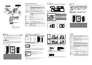
Product Profile and Outline
90.00
4.00
3.00
25.20
60.00
1
2
3
4
5
6
7
8
9
3
10
11
12
13
STOP
RUN
ERROR
RUN
POWER
X6
X7
C0
Y5
Y4
Y3
Y2
Y1
Y0
C2
C1
X5
X4
X3
X2
X1
X0
s
s
14
1. POWER, RUN, ERROR indicator 8. Extension port
2. I/O port for program communication (RS-232) 9. Extension unit clip
3. DIN rail clip 10. DIN rail (35mm)
4. I/O terminals 11. RS-485 communication port
5. I/O point indicator 12. Mounting rail for extension unit
6. Mounting hole for extension unit 13. DC power input
7. Nameplate 14. RUN/STOP switch
ENGLISH
Electrical Specifications
Model
Item
DVP14SS11R/T
Power supply voltage
MPU: 24V DC (-15%~20%) (With DC input reverse polarity protection)
Fuse
2A/250V AC
Power Consumption
3.5W
Insulation Resistance
> 5 M at 500 V DC (Between all inputs / outputs and earth)
Noise Immunity
ESD: 8KV Air Discharge
EFT: Power Line: 2KV, Digital I/O: 1KV, Analog & Communication I/O: 250V
Damped-Oscillatory Wave: Power Line: 1KV, Digital I/O: 1KV
RS: 26MHz ~ 1GHz, 10V/m
Grounding
The diameter of grounding wire cannot be smaller than the wire diameter of
terminals L and N (All DVP units should be grounded directly to the ground pole).
Environment
Operation: 0°C ~ 55°C (temperature), 50 ~ 95% (humidity), pollution degree 2;
Storage: -25°C ~ 70°C (temperature), 5 ~ 95% (humidity)
Vibration / Shock Resistance
Standard: IEC61131-2, IEC 68-2-6 (TEST Fc)/IEC61131-2 & IEC 68-2-27 (TEST Ea)
Weight (approx.) (g)
214(g)/208(g)
Approvals
Input Point Electrical Specification
Input Type DC (SINK or SOURCE)
Input Current 24V DC 5mA
Off → On,
X0, X1: 18.5V DC and above
X2 ~ X7: 16.5V DC and above
Active Level
On → Off,
X0 ~ X7: below 8V DC
Response Time
About 10ms (An adjustment range of 0 ~ 20ms could be selected through D1020 and
D1021)
Output Point Electrical Specification
Output Type Relay-R Transistor-T
Current Specification 1.5A/1 point (5A/COM)
55°C 0.1A/1point, 50°C 0.15A/1point
45°C 0.2A/1 point, 40°C 0.3A/1 point (2A/COM
Voltage Specification Below 250V AC, 30V DC
30V DC
75VA (inductive)
Maximum Loading
90W (resistive)
9W/1 point
Response Time About 10ms
Off On 20us
On Off 30us
Model Name & I/O Configuration
Input / Output
Input Unit Output Unit Model
Power
Point
Type Point
Type
Profile reference I/O Configuration
DVP14SS11R2
8 6 Relay
DVP14SS11T2
24V DC
8
DC Sink or
Source
6 Transistor
S/S
X0
X1
X2
X3
X4
X5
X6
X7
C0
Y0
C1
C2
Y1
Y2
Y3
Y5
Y4
Installation & Wiring
4.1 PLC Mounting Arrangements and Wiring Notes
DVP MPU
50m m
50m m
50mm
50m m
Please install PLC in an enclosure with sufficient space around it to allow
heat dissipation as shown in the figure.
How to install DIN rail:
DVP-PLC can be secured to a cabinet by using the DIN rail of 35mm in height and 7.5mm in depth. When
mounting PLC to DIN rail, be sure to use the end bracket to stop any side-to-side movement of PLC and reduce
the chance of wires being loosen. A small retaining clip is at the bottom of PLC. To secure PLC to DIN rail, place
the clip onto the rail and gently push it up. To remove it, pull the retaining clip down and gently remove PLC from
DIN rail, as shown in the figure.
Wiring:
22-16AWG
<1.5mm
1. Use the 22-16AWG (1.5mm) single-core bare wire or the multi-
core
wire for the I/O wiring, and the specifications of the terminal are
shown diagram on the left.
The twisting power of the screw for the
PLC terminal is 1.95 kgf-cm (1.7 lb-in).
2.
DO NOT place the input signal cable and output power cable in the
same wiring circuit.
3. Use only 60/75ºC copper conductor.
4.2 Wiring Notes
Environment
1. DO NOT store the PLC in an atmosphere that is dusty, smoky, with metallic debris or corrosive or flammable
gases.
2. DO NOT store the PLC in an environment with high temperature or high humidity.
3. DO NOT install the PLC on a shelf or on an unstable surface.
Power Input Wiring
DVP-SS uses DC input power. Therefore, make sure that DVP-SS is connected to terminals 24V DC and 0V
(power range 20.4 ~ 28.8V DC) when the power is ON. DVP-SS will stop the operation and the output will be
OFF whenever the power input is lower than 20.4V DC. Consequently, the ERROR LED will blink swiftly.
S/S
X0 X1 X2+24V 24 GOV24VDC
DC/DC
2.5A
5V
20.4VD C~28.8VDC
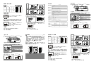
Safety Wiring
Since a PLC controls many devices, actions of any device may affect actions of other devices, and the
breakdown of any one device may cause the breakdown of the whole auto-control system and danger.
Therefore, we suggest you wire a protection circuit at the power input terminal, as shown in the figure below.
AC power supply load
Power circuit protection fuse (2A)
Power indicator
Emergency stop
This button can cut off the system power supply when
accidental emergency takes place.
System circuit isolation device
The device is made of electromagnetic contactor and relay
as the switch to prevent the instability of system when the
power is intermittently supplied.
DVPPS01/24V DC power module
DVP-PLC
MC
MC
1
2
3
L
N
5
4
1
24V
0V
8
Guard
Lim it
6
7
24V
0V
Power supply: 24V DC
Input Point Wiring
There are two types of DC inputs, SINK and SOURCE.
Two types of DC wiring are used: SINK and SOURCE, defined as follows:
Sink = common port for current input S/S Source = common port for current output S/S
Sin king
S/S
X0
Sourcing
S/S
X0
Input point loop equivalent circuit Wiring loop
DC Type
(DC Signal IN)
SINK Mode
24VDC
0V
X0
S/S
+24V
SINK
+5V
OV
S/S
X0
X1
X2
+24V
Sink Type
24VDC
Input point loop equivalent circuit Wiring loop
DC Type
(DC Signal IN)
SOURCE Mode
24VDC
0V
X0
S/S
+24V
SOUR CE
+5V
0V S/S X0 X1 X2+24V
Source Type
24VDC
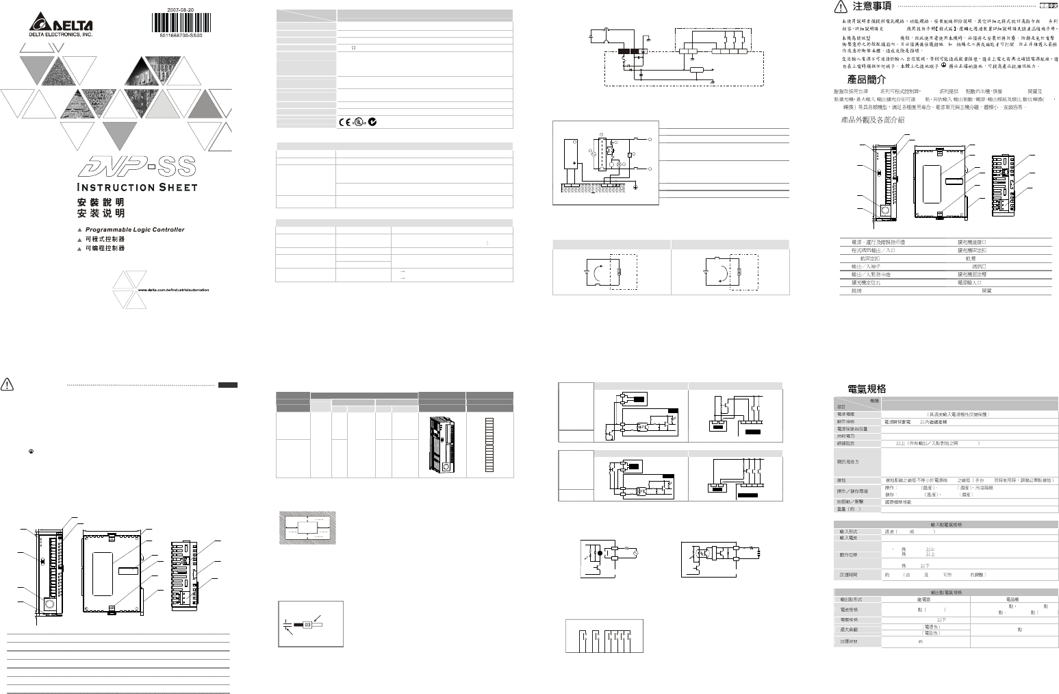
Output Point Wiring
Every output contact possesses a overload capacity that is twice as much as the rated current for 5
minutes. The exceeded range may result in contact malfunction and even the burn-down of internal
circuit.
Y0
RY
LED
C0
LOAD
POWER
DVP-**-**-11-R
RELAY OUTPUT
DVP-**-**-11-T
TRANSISTOR OUTPUT
LED
Y0
C0
LOAD
< 0.3A
T
R
G
1. Two types of DVP-SS series PLC output modules: Relay or Transistor. For the electrical specification,
please refer to the function specification.
2. Please watch out the connection of common terminals while wire the outputs. For example, when
wiring DVP14SS11R, output terminal Y0 uses one common terminal C0, Y1 uses C1, and Y2 ~ Y5
share C2, as shown below:
C0
Y0
C1
Y1
C2
Y2
Y3
Y4
Y5
Action indication: When the output point is active, the corresponding indicator at the front panel will be
on.
3. Isolated circuit: The optical coupler is used to isolate signals between PLC internal circuits and input
modules.
ES
DVP-PLC
(OPEN TYPE) /
( : )
/
DVP DVP-SS 14 RUN/STOP 8 ~ 16
/ 128 / / A/D
D/A
90.00
4.00
3.00
25.20
60.00
1
2
3
4
5
6
7
8
9
3
10
11
12
13
STOP
RUN
ERROR
RUN
POWER
X6
X7
C0
Y5
Y4
Y3
Y2
Y1
Y0
C2
C1
X5
X4
X3
X2
X1
X0
s
s
14
1. 8.
2. (RS-232) 9.
3. DIN 10. DIN (35mm)
4. 11. RS-485
5. 12.
6. 13.
7. 14. RUN/STOP
DVP14SS11R/T
24V DC (-15% ~ 20%)
5ms
2A/250V AC
3.5W
5 MΩ 500V DC
ESD (IEC 61131-2, IEC 61000-4-2): 8KV Air Discharge
EFT (IEC 61131-2, IEC 61000-4-4): Power Line: 2KV, Digital I/O: 1KV, Analog &
Communication I/O: 1KV
Damped-Oscillatory Wave: Power Line: 1KV, Digital I/O: 1KV
RS (IEC 61131-2, IEC 61000-4-3): 26MHz ~ 1GHz, 10V/m
L, N PLC
0°C ~ 55°C 50 ~ 95% 2
-40°C ~ 70°C 5 ~ 95%
IEC61131-2, IEC 68-2-6 (TEST Fc)/IEC61131-2 & IEC 68-2-27 (TEST Ea)
,g
214 (g)/208 (g)
SINK SOURCE
24VDC 5mA
Off → On,
X0 X1 18.5V DC
X2 ~ X7 16.5V DC
On → Off,
X0 ~ X7 8V DC
10 ms D1020 D1021 0 ~ 20ms
-R -T
1.5A/1 5A/COM
55°C 0.1A/1 50°C 0.15A/1
45°C 0.2A/1 40°C 0.3A/1 2A/COM
250VAC,30VDC
30V DC
75VA
90 W
9W/1
10 ms
Off → On 15us
On → Off 25us