


Warning
Please read this instruction carefully before use and follow this instruction to operate the device in order to prevent
damages on the device or injuries to staff.
Switch off the power before wiring.
This instruction sheet only provides introductory information on electrical specification, functions, wiring,
trouble-shooting and peripherals for IFD9502. Details of DeviceNet protocol are not included in this sheet. For
more information on DeviceNet Protocol, please refer to relevant reference or literatures.
IFD9502 is an OPEN-TYPE device and therefore should be installed in an enclosure free of airborne dust, humidity,
electric shock and vibration. The enclosure should prevent non-maintenance staff from operating the device (e.g. key
or specific tools are required to open the enclosure) in case danger and damage on the device may occur.
IFD9502 is to be used for controlling the operating machine and equipment. In order not to damage it, only qualified
professional staff familiar with the structure and operation of it can install, operate, wire and maintain it.
DO NOT connect input AC power supply to any of the I/O terminals; otherwise serious damage may occur. Check all
the wiring again before switching on the power and DO NOT touch any terminal when the power is switched on.
Make sure the ground terminal is correctly grounded in order to prevent electromagnetic interference.
Introduction
Thank you for choosing Delta IFD9502 DeviceNet Slave Communication Module. IFD9502 can be applied to
the connection between DeviceNet and Delta’s programmable logic controllers, AC motor drives, servo drives,
temperature controllers and human machine interfaces. In addition, IFD9502 offers custom function, which can
be applied to the connection between DeviceNet and self-defined equipment with Modbus protocol.
Functions
Supports Group 2 only servers
Supports explicit connection in the pre-defined
master/slave connection group
Supports polling
Supports EDS files in DeviceNet network
configuration tools
Product Profile & Outline
Unit: mm
1
Communication port
2
Address setup rotary switch
3
Function setup DIP switch
4
Instruction on function setup switch
5
SP (Scan Port) indicator
6
MS (Module Status) indicator
7
NS (Network Status) indicator
8
DeviceNet connector
DIN rail
DIN rail clip
Specifications
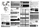
DeviceNet Connector
Type Removable connector (5.08mm)
Transmission method CAN
Transmission cable 2 communication cables, 2 power cables and 1 shielded cable
Electrical isolation 500V DC
1
2
3
4
5
6
7
8
9
10
ENGLISH
Communication
Message type I/O polling; explicit
Series transmission
speed
125kbps; 250kbps; 500kbps
Equipment type 12
Company ID 799 (Delta Electronics, Inc.)
Electrical Specifications
Voltage 11 ~ 25V DC (offered by the power cable in the network)
Current 28mA (typical), 125mA impulse current (24V DC)
Environment
Standards IEC 61131-2, UL508
Storage/Operation
Storage: -25°C~70°C (temperature), 5~95% (humidity)
Operation: 0°C~55°C (temperature), 50~95% (humidity); pollution degree 2
Shock/Vibration
immunity
International Standards: IEC 61131-2, IEC 68-2-6 (TEST Fc)/IEC 61131-2 &
IEC 68-2-27 (TEST Ea)
Interference immunity
RS (IEC 61131-2, IEC 61000-4-3): 80MHz~1,000MHz, 1.4GHz~2GHz,10V/m
EFT (IEC 61131-2, IEC 61000-4-4): Analog & Communication I/O: 1KV
ESD (IEC 61131-2, IEC 61000-4-2): 8KV Air Discharge
Certificates CE, UL
Installation & Wiring
Install IFD9502 in an enclosure with sufficient space around it to
allow heat dissipation (see the figure).
DO NOT place the I/O signal wires and power supply wire in the
same wiring circuit.
<1.5mm
28-12AWG
Use 28-12AWG (1.5mm) single or multiple core wire on I/O wiring terminals.
See the figure for its specification.
The terminal screws shall be tightened to 4.75 kg-cm (4.12 in-lbs).
Use 60°C /75°C copper wires only.
Components
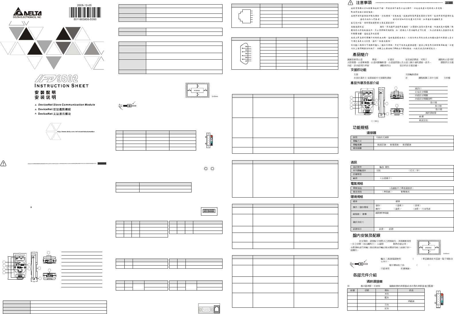
DeviceNet Connector
To connect to the DeviceNet network, use the connector enclosed with IFD9502 or any connectors you can
buy in the store for wiring.
PIN Signal Color Description
1 V- Black 0V DC
2 CAN_L Blue Signal-
3 SHIELD --- Shielded cable
4 CAN_H White Signal+
5 V+ Red 24V DC
1
2
3
4
5
Address Switch
The two rotary address setup switches set up the node addresses on DeviceNet
network in decimal form. Setup range: 00 ~ 63 (64 ~99 are forbidden)
5
0
x10
1
0
x10
5
0
Example:
If you need to set the node address of IFD9502 to 26, simply switch the corresponding rotary switch of X10
1
to
“2” and the corresponding rotary switch of X10
0
to “6”
Address Setting Description
0…63 Valid DeviceNet node address
Others Invalid DeviceNet node address
Note: The changed values on switches are only valid when IFD9502 is re-powered. When IFD9502 is operating,
changing the set value of node address will be invalid.
Function Switch
The DIP switch is to be used on the equipment connected to IFD9502, the sele
ction
of communication ports and setting up the baud rate of IFD9502 and the Master
station in DeviceNet.
1 2 3 4 5 6 78
SW3
DIPON
Selecting the Equipment Connected to IFD9502
PIN1
PIN2
PIN3
Equipment
PIN1
PIN2
PIN3
Equipment
ON OFF OFF AC motor drive
ON OFF ON Human machine interface
OFF
ON OFF PLC
OFF ON ON Custom equipment
ON ON OFF Temperature controller
ON ON ON For internal system use
OFF OFF ON Servo drive
Example:
If the equipment connected to IFD9502 is a Delta servo drive, you only need to switch PIN 3 to “ON”, PIN 1 and
PIN 2 to “OFF” and re-power it.
Note:
The changed setting of the switch is only valid when IFD9502 is re-powered. When IFD9502 is operating,
changing the setting of DIP switch will be invalid.
Selecting IFD9502 Communication Mode
PIN4 PIN5 Communication Mode
PIN4
PIN5
Communication Mode
OFF OFF RS-485
ON OFF Incorrect setting
ON ON RS-232
OFF ON Incorrect setting
Note:
The changed setting of communication mode is only valid when IFD9502 is re-powered. When IFD9502 is
operating, changing the setting of communication mode will be invalid.
Setting up Baud Rate
PIN 6
PIN7 PIN8 Baud Rate
PIN 6
PIN7
PIN8 Baud Rate
OFF OFF 125kbps OFF ON 500kbps
ON OFF
Reserved
250kbps
ON ON
Reserved
Auto baud rate detection
Note:
The changed setting of the baud rate of DeviceNet is only valid when IFD9502 is re-powered. When IFD9502 is
operating, changing the communication speed will be invalid.
Communication Ports on IFD9502
The communication ports on IFD9502 are used for the connection to equipment
(Delta PLC, Delta AC motor drive, Delta temperature controller, Delta servo drive,
Delta human machine interface and custom equipment)
PORT1
PORT2
PORT 1
PORT 1 Sketch Terminal No. Description
1 N.C.
2 GND
3 DATA-
4 DATA+
5 N.C.
1
2
3
4
5
6
PORT1
6 N.C.
Note:
PORT 1 supports RS-485 communication mode only.
PORT 2
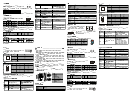
PORT 2 Sketch Terminal No. RS-232 RS-485
1 N.C. N.C.
2 RXD N.C.
3 TXD DATA-
4 N.C. N.C.
5 GND GND
6 N.C. N.C.
7 N.C. N.C.
8 N.C. DATA+
1
6
2
7
3
8
4
9
5
DB9 male
9 N.C. N.C.
Note:
PORT 2 supports RS-232 and RS-485 communication mode only.
LED Indicators & Troubleshooting
There are 3 LED indicators on IFD9502, Network Status LED, Module Status LED and Scan Port LED, for
displaying the connection status of the communication.
Network Status LED
LED status Indication How to deal with it?
OFF
Device is not on-line.
- The device has not completed the
Dup_MAC_ID test yet.
- The device may not be powered.
1.
Check the power of IFD9502 and see if the
connection is normal.
2. Check if the node communication on the
BUS is normal.
3. Make sure at least 1 node is normally
communicating with the network through
IFD9502.
Green light flashes
Device is on-line but has no connections
in the established state.
- The device has passed the
Dup_MAC_ID test, is on-line, but has
no established connections to other
nodes.
- This device is not allocated to a master.
---
Green light ON
The device is on-line and has
connections in the established state.
- The device is allocated to a Master.
---
Red light flashes
I/O Connections are in the timed-out
state.
---
LED status Indication How to deal with it?
Red light ON
Failed communication device. The device
has detected an error that has rendered
it
incapable of communicating on the
network (Duplicate MAC ID fail, or
Bus-off).
1. Make sure all the node addresses on the
BUS are not repeated.
2. Check if the network installation is normal.
3. Check if the communication speed of
IFD9502 is consistent with that of the BUS.
4. Check if the station No. of IFD9502 is
valid.
5. Check if your choice of switch on IFD9502
is consistent with the actual connected the
equipment.
6. Check if IFD9502 is correctly wired with
the equipment.
Module Status LED
LED status Indication How to deal with it?
OFF There is no power applied to the device.
Check the power of IFD9502 and see if the
connection is normal.
Green light flashes
The device needs commissioning due to
configuration missing, incomplete or
incorrect.
The device may be in the standby state.
-
Green light ON
The device is operating in a normal
condition.
-
Red light flashes Recoverable fault
1. Reset parameters in IFD9502.
2. Check if IFD9502 is correctly wired with
the equipment.
Red light ON
The device has an unrecoverable fault;
may need replacing.
Send back to factory for repair.
Scan Port Status LED
LED Status Indication How to deal with it
OFF Power is off
Check the power of IFD9502 and see if the
connection is normal.
Green light flashes
IFD9502 is reading the preset value in
the equipment. IFD9502 obtains the
parameters from the equipment and
initializes some of the attributes.
-
Green light ON
Communication between IFD9502 and
the equipment is normal.
-
Red light flashes
CRC check fails, or the equipment sen
ds
back error information.
1. Check if the communication format of the
equipment is correctly set up.
2. Check carefully if the installation is correct.
Red light ON Connection fails, or no connection.
1. Check if IFD9502 is correctly connected
with the equipment.
2. Restart the connection and make sure the
communication cable meets the
specification.
IFD9502 DeviceNet DeviceNet
(OPEN TYPE)
( )
IFD9502 IFD9502 DeviceNet DeviceNet
IFD9502
DeviceNet Modbus
Group 2 only servers
/
DeviceNet EDS
: mm
1
2
3
4
5
SP (Scan Port)
6
MS (Module Status)
7
NS (Network Status)
8
DeviceNet
DIN
DIN
DeviceNet
(5.08mm)
CAN
2 2 1
500V DC
1
2
3
4
5
6
7
8
9
10
I/O
125kbps; 250kbps; 500kbps
12
ID 799
11 ~ 25V DC
28mA 125mA (24V DC)
IEC 61131-2,UL508
-25°C ~ 70°C 5 ~ 95%
0°C ~ 55°C 50 ~ 95% 2
/
IEC 61131-2, IEC 68-2-6 (TEST Fc)/IEC 61131-2 & IEC 68-2-27
(TEST Ea)
RS (IEC 61131-2, IEC 61000-4-3): 80MHz ~ 1,000MHz, 1.4GHz ~ 2GHz, 10V/m
EFT (IEC 61131-2, IEC 61000-4-4): Analog & Communication I/O: 1KV
ESD (IEC 61131-2, IEC 61000-4-2): 8KV Air Discharge
CE UL
IFD9502
IFD9502
<1.5mm
28-12AWG
/ 28-12AWG 1.5mm
IFD9502 4.75 kg-cm 4.12 in-lbs
60°C/75°C
DeviceNet
DeviceNet IFD9502
1 V-
0V DC
2 CAN_L
Signal-
3 SHIELD -
4 CAN_H
Signal+
5 V+
24V DC
1
2
3
4
5